In order to promote public education and public safety, equal justice for all, a better informed citizenry, the rule of law, world trade and world peace, this legal document is hereby made available on a noncommercial basis, as it is the right of all humans to know and speak the laws that govern them.
SURFACE VEHICLE RECOMMENDED PRACTICE
Submitted for recognition as an American National Standard
 , J1100 REV. FEB2001
Issued 1973-09
Revised 2001-02
Superseding J1100 JUN1998
1. Scope—This SAE Recommended Practice defines a uniform set of interior and exterior dimensions for passenger cars, multipurpose passenger vehicles, and trucks.
2. References
2.1 Applicable Publications—The following publications form a part of the specification to the extent specified herein. Unless otherwise indicated, the latest revision of SAE publications shall apply.
2.1.1 SAE PUBLICATIONS—Available from SAE, 400 Commonwealth Drive, Warrendale, PA 15096-0001.
SAE J182—Motor Vehicle Fiducial Marks
SAE J826—Devices for Use in Defining and Measuring Vehicle Seating Accommodation
SAE J941—Motor Vehicle Driver's Eye Range
SAE J1052—Motor Vehicle Driver and Passenger Head Position
SAE E-7
3. Definitions
3.1 Motor Vehicles—Classifications are made both according to vehicle use definitions and to interior seating dimensions.
3.1.1 PASSENGER CAR—Vehicles with motive power, except multipurpose passenger vehicles, motorcycles, or trailers, designed for carrying 10 persons or less.
3.1.1.1 Station Wagon—Passenger Cars with an extended upper to increase the cargo and/or passenger capacity.
3.1.1.2 Hatchback—Passengers Cars with the rear access door encompassing the back light.
3.1.2 MULTIPURPOSE, PASSENGER VEHICLE (MPV)—Vehicles with motive power, except trailers, designed to carry 10 persons or less, which are constructed either on a truck chassis or with special features for occasional off-road operation.
3.1.3 TRUCK—Vehicles with motive power, except a trailer, designed primarily for the transportation of property or special-purpose equipment.
SAE Technical Standards Board Rules provide that: “This report is published by SAE to advance the state of technical and engineering sciences. The use of this report is entirely voluntary, and its applicability and suitability for any particular use, including any patent infringement arising therefrom, is the sole responsibility of the user.”
SAE reviews each technical report at least every five years at which time it may be reaffirmed, revised, or cancelled. SAE invites your written comments and suggestions.
TO PLACE A DOCUMENT ORDER: (724)776-4970 FAX:(724) 776-0790
SAE WEB ADDRESS http://www.sae.org
Copyright 2001 Society of Automotive Engineers, Inc.
All rights reserved.
Printed in U.S.A.
13.1.3.1 Light Truck—Classification of self-propelled vehicles which are designed primarily to transport property or special-purpose equipment, and have a maximum gross vehicle weight rating (GVWR) of 4536 kg (10 000 1b) or less.
GVWR is the value specified by the vehicle manufacturer as the loaded weight of a single vehicle.
3.1.3.2 Heavy Truck—Classification of self-propelled vehicles which are designed primarily to transport property or special purpose equipment, and have a gross vehicle weight rating over 4536 kg (10 000 1b).
3.1.4 Two distinct vehicle groupings are derived according to driver seating arrangement dimensions.
3.1.4.1 Class A Vehicles
(H30)—Vertical SgRP to Heel Point—(127 to 405 mm)
(H59)—Vertical H-Point Rise—(0.0 to 50 mm)
(L23)—Normal Driving and Riding Seat Track Travel—(greater than 100 mm)
(W9)—Steering Wheel Diameter—(less than 450 mm)
(L40)—Torso Angle −Front—(5 to 40 degrees)
3.1.4.2 Class B Vehicles
(H30)—Vertical SgRP to Heel Point—(405 to 530 mm)
(H59)—Vertical H-Point Rise—(0 mm)
(L23)—Normal Driving and Riding Seat Track Travel—(greater than 100 mm)
(W9)—Steering Wheel Diameter—(450 to 560 mm)
(L40)—Torso Angle—(11 to 18 degrees)
3.2 Vehicle Weights—Specific Vehicle Weights with the addition of specified loads are defined as follows. These Vehicle Weights are established to enable uniform static comparisons of dimensions affected by the ground plane and vehicle pitch (attitude).
3.2.1 CURB WEIGHT—The weight of a motor vehicle with standard equipment only: maximum capacity of engine fuel, oil, and coolant. For heavy trucks, the weight does not include engine fuel.
3.2.2 DESIGN LOAD WEIGHT—Passenger Car-Curb weight, plus passengers and luggage or cargo load as specified by manufacturer, each passenger weighing 68 kg (150 1b).
3.2.3 DESIGN LOAD WEIGHT/HEIGHT-TRUCKS AND MPV's—The height of a motor vehicle with the front and rear suspension at the manufacturer's design-loaded condition and the front and rear loaded to then rated capacity.
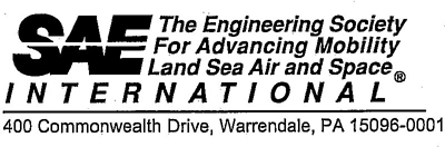
3.3 Coordinate Dimension—All points of interests are described as coordinates dimensioned from the intersection of the zero planes in the three-dimensional reference system. X, Y, Z coordinates are dimensioned to their respective planes. (See Figure 1.)
3.4 Vehicle Fiducial Marks—See SAE J182. These are holes, surfaces, marks, or indentations on the vehicle body as described by the manufacturer. Their location is specified in the three-dimensional reference system by X, Y, Z coordinates and to ground with the vehicle at a specified Vehicle Weight.
2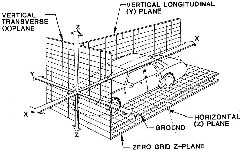
FIGURE 1—THREE-DIMENSIONAL REFERENCE SYSTEM
3.5 Eyellipse—See SAE J941.
3.6 Two-and Three-Dimensional Devices—See SAE J826.
3.7 Head Position Contour—See SAE J1052.
3.8 Head Contour Locator Line-Fixed Seat—See SAE J1052.
3.9 Eyellipse and Head Contour Locator Line—See SAE J941.
3.10 T-Point—Any point on the Head Contour Locator Line-Fixed (Seat see 3.8).
3.11 H-Point—The H-Point is the Pivot Center of the torso and thigh on the Two-or Three-Dimensional devices used in defining and measuring vehicle seating accommodation (see SAE J826).
3.11.1 DESIGN H-POINT—The Design H-Point is located on a drawing by the H-Point on the two-dimensional drafting template placed in any designated seating position. If the designated seating position can be adjusted, the path of the Design H-Point through the full seat adjustment establishes the Design H-Point travel path, and can be dimensionally described by coordinates relative to the three-dimensional reference system. (See Section 14.)
33.11.2 SEATING REFERENCE POINT (SGRP)—The manufacturer's design reference point is a unique Design H-Point which:
3.11.3 ACTUAL H-POINT—The actual H-Point is located in an actual vehicle by the H-Point on the three-dimensional H-Point Machine with the 95th percentile leg installed in any designated seating position per instruction in SAE J826 and can be dimensionally located by coordinates relative to the three-dimensional reference system.
3.12 Designated Seating Position—Any plan view location intended by the manufacturer to provide seating accommodation while the vehicle is in motion, for a person at least as large as a 5th percentile adult female, except auxiliary seating accommodations such as temporary or folding jump seats.
3.13 D-Point—D-Point is the lowest point on the buttocks contour of the seated Two-or Three-Dimensional Device in the installed position. (See Figure 2.)
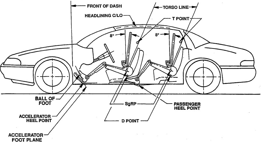
FIGURE 2—REFERENCE POINTS
3.14 Cowl Point—Cowl Point is a point on the exterior windshield glazing surface on the zero “Y” plane at the highest height of the Cowl, Hood, or exterior components. (See Figure 3.)
3.15 Deck Point—Deck Point is a point on the exterior rear-window glazing surface on the zero “Y” plane at the highest height of the Deck Lid Panel, or exterior components. (See Figure 3.)
4
FIGURE 3—DLO AND EXTERIOR DIMENSIONS, LENGTH
3.16 Foot Pedal References—(See Figure 2.)
3.16.1 ACCELERATOR HEEL POINT (AHP)—The lowest point at the intersection of the manikin heel and the Depressed Floor Covering with the shoe on the Undepressed Accelerator Pedal. The foot angle (L46) is at a minimum of 87 degrees with the manikin H-Point at the SgRP. For vehicles with SgRP to heel vertical (H30) greater than 405 mm, the accelerator pedal may be depressed as specified by the manufacturer. If the depressed pedal is used, the foot must be flat on the accelerator pedal.
3.16.2 BALL OF FOOT (BOF)—A point on a straight line tangent to the bottom of the manikin—s shoe in side-view 203 mm from the Accelerator Heel Point. The lateral (Y coordinate) location for the Ball of Foot is mid-width on the shoe at the side view Ball of Foot location.
53.16.3 ACCELERATOR FOOT PLANE (AFP)—A plane passing through the Accelerator Heel Point (AHP) and the Ball of Foot (BOF) that is normal to the Y plane.
3.17 Centerline of Occupant (C/LO)—Centerline of Occupant is the “Y” coordinate of the center plane of the occupant in each designated seating position.
3.18 Torso Line—Torso Line is the line on the two-dimensional drafting template connecting the shoulder reference point-SAE J826 and the H-Point (corresponds to centerline of head room probe in full back position of H-Point machine). The Torso Line is parallel to the straight (flat) portion of the lower back on the torso and is used to facilitate the definition of torso angle.
3.19 Front of Dash—Front of Dash represents a vertical tangent to the foremost predominating surface of the dash panel at the centerline of driver, disregarding flanges and small localized formations. The dash panel is usually the vertical extension of the toe panel.
3.20 Undepressed Floor Covering—Undepressed Floor Covering is the surface of the floor covering at a designated point on the vehicle without any load applied to the covering.
3.21 Depressed Floor Covering—Depressed Floor Covering is the surface of the floor covering at a designated point in the vehicle, with a load applied to the covering as specified by the manufacturer.
3.22 Daylight Opening DLO—Daylight Opening is a line on the exterior glazing surface that defines the minimum unobstructed opening through any glass aperture, including opaque coatings, reveal or garnish moldings adjoining the glass, according to a given direction or projection. Opaque coatings, reveal or garnish moldings adjoining the interior glazing surface are projected horizontally to the interior glazing surface, then normal and outward to the exterior glazing surface. Exterior components are projected horizontally to the exterior glazing surface (see Figure 3).
3.23 Thigh Centerline—Line connecting H-Point and Knee Pivot Point. (See SAE J826.)
3.24 Cushion Line—Cushion Line is the Thigh Centerline on the H-Point machine when installed without the lower legs and the Torso Weights redistributed about the seat pan. Cushion Line is used to facilitate the definition of Cushion Angle which reflects the attitude that the Seat Cushion imposes on the seated occupant's thighs. (See SAE J826.)
3.25 Leg Centerline—Line connecting Knee Pivot Point and Ankle Pivot Point. (See SAE J826.)
3.26 Normal Top of Frame-Truck—The Longest normal surface of the top flange of the truck frame within the wheel base.
3.27 Cargo Floor—The surface for supporting cargo including ribs, or Undepressed Floor Covering.
4. General—The dimensions in this report will enable the measurement of a vehicle as designed. The prefix “A” may precede a dimension taken from a vehicle as built, which will enable a comparison between vehicles as designed and/or built.
All dimensions are defined normal to the three-dimensional reference system, described in SAE J182 except for ground-related dimensions which are defined normal to ground with the vehicle loaded to a design load weight, unless defined in the dimension definition.
All dimensions are measured to the base vehicle and do not include Regular Production Options (RPO) or accessory parts, unless defined by the dimension definition.
6The dimensions in this document are classified in groups of relevant interest. Each dimension is assigned a code which is composed of a prefix letter denoting the direction or type of dimension and a number issued in sequence as required by each prefix letter. The code is interpreted as follows:
NOTE—# in front of dimension code indicates a change from the previous version of SAE J1100.
The prefix letter:
W-Width dimensions
H-Height dimensions
PD-Passenger distribution dimensions
L-Length dimensions
S-Surface are dimensions
SD-Seal facing direction dimensions
V-Volume dimensions
PL-Pedal Lengths (sizes & clearances)
PW-Pedal Widths (sizes & clearances)
PH-Pedal Heights (sizes & clearances)
TL-Length dimensions-H-Point Location & Travel
The-Height dimensions-H-Point Location & TravelThe number:
1-99 Interior dimensions
100-199 Exterior dimensions
200-299 Cargo or luggage dimensions
300-399 Interior dimensions-Unique for Truck and MPV's
400-499 Exterior dimensions-Unique for Truck and MPV's
500-599 Cargo Dimensions-Unique for Truck and MPV'sTo assist in locating dimensions in this document, numeric and alphabetic sequences are shown in Sections 15 and 16.
4.1 Interior Dimensions—All Interior Dimensions are defined with an adjustable front seat in its rearmost normal driving position, resulting in the Design H-Point being positioned at the Seating Reference Point (SgRP) position. All other adjustable features, such as an adjustable steering wheel and adjustable seat height, a seatback that adjusts independently from the Seat Cushion, power 4-way or 6-way seats, etc., shall be positioned in their normal driving position as specified by the manufacturer. Steering wheel shall be positioned with from the wheels in straight-ahead position.
7All interior dimensions for designated seated positions are defined on the Y-Plane centerline of the occupant, unless otherwise defined in the dimensions definition. The H-Point machine and two-dimensional drafting template specified in SAE J826 shall use the 95th percentile leg segments.
For heavy-duty trucks, suspension seats will be positioned as specified by the vehicle manufacturer in the normal driving position with any fore and aft isolator locked out.
4.2 Exterior Dimensions—All exterior dimensions terminate at the outside surface of the sheet metal, bumper, or integral moldings, unless otherwise specified. The front wheels shall be positioned in the straight-ahead position. All exterior dimensions define the proportional shape of the vehicle, as opposed to its designed pieces. For example, when two vehicles with the same front end profile are designed, one with a bolt on bumper and one with bumper integrated with the front end, the front end length dimension (L126) on both vehicles will be the same.
4.3 Cargo Dimensions—All dimensions are measured with the front seat positioned the same as the interior dimensions and all rear seats folded as specified by the manufacturer. All head restraints shall be in the stowed position and considered part of the seat.
4.4 Luggage Capacity—The Luggage Capacity will be measured with the use of simulated luggage described in 8.1 and properly installed, detailed in 9.2, in a luggage compartment separate from the passenger compartment.
4.5 The ISO Cargo Volume—Measuring methods allow for cargo volume comparisons with non-U.S. vehicles using ISO standards. (Refer to Section 11.)
5. Fiducial Mark Dimensions
5.1 Fiducial Mark-Number 1
L54-“X” coordinate
W21-“Y” coordinate
H81-“Z” coordinate
H161-Height “Z” coordinate to ground at curb weight
H163-Height-Height “Z” coordinate to ground
5.2 Fiducial Mark-Number 2
L55-“X” coordinate
W22-“Y” coordinate
H82-“Z” coordinate
H162-Height “Z” coordinate to ground at curb weight
H164-Height “Z” coordinate to ground
5.3 Fiducial Mark-Number 3
L56-“X” coordinate
W23-“Y” coordinate
H167-Height “Z” coordinate to ground at curb weight
H168-Height “Z” coordinate to ground
6. Interior Dimensions
6.1 Front Seat Compartment Dimensions—Driver unless otherwise specified. (See Figures 4 through 12.)
6.1.1 PD1-PASSENGER DISTRIBUTION-FRONT
6.1.2 H5-SGRP-FRONT TO GROUND—The dimension measured vertically from the SgRP to ground.
8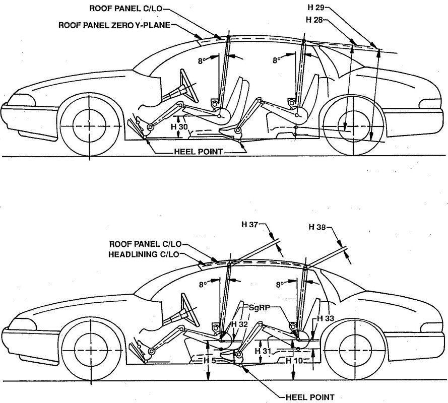
FIGURE 4—INTERIOR DIMENSIONS, HEIGHT
9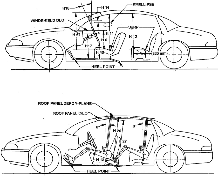
FIGURE 5—INTERIOR DIMENSIONS, HEIGHT
10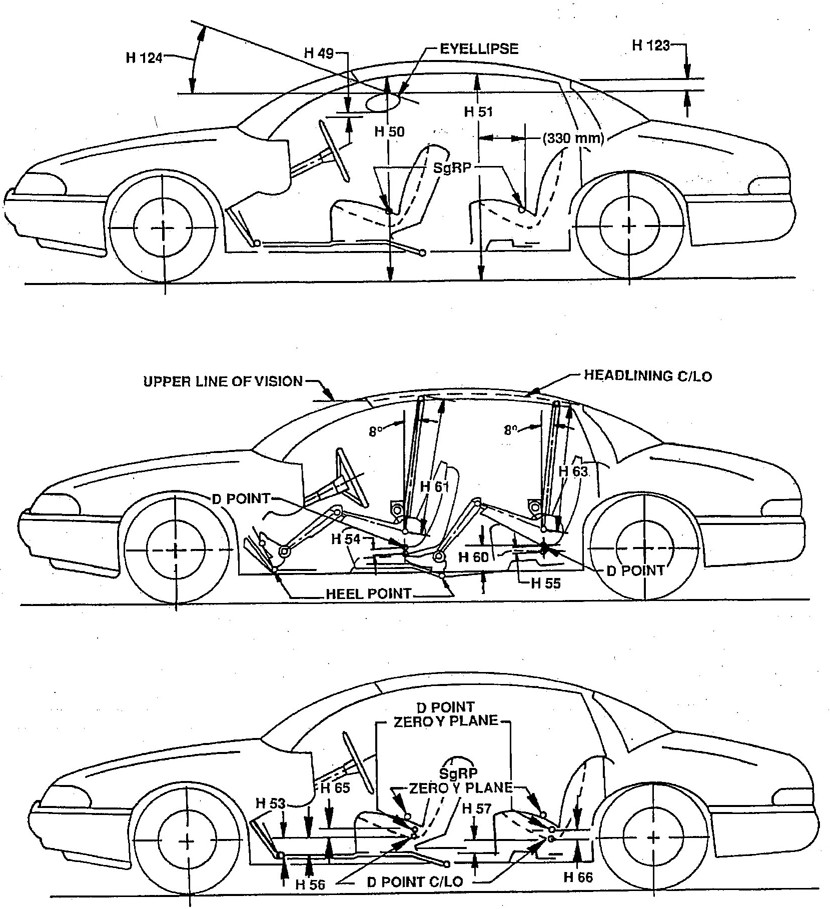
FIGURE 6—INTERIOR DIMENSIONS, HEIGHT
11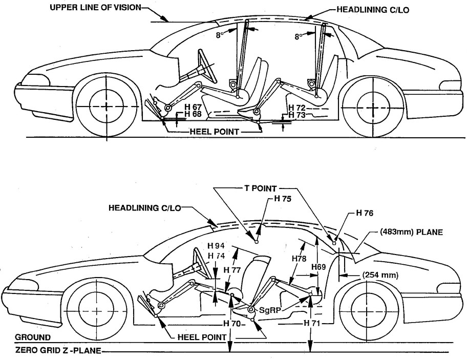
FIGURE 7—INTERIOR DIMENSIONS, HEIGHT
12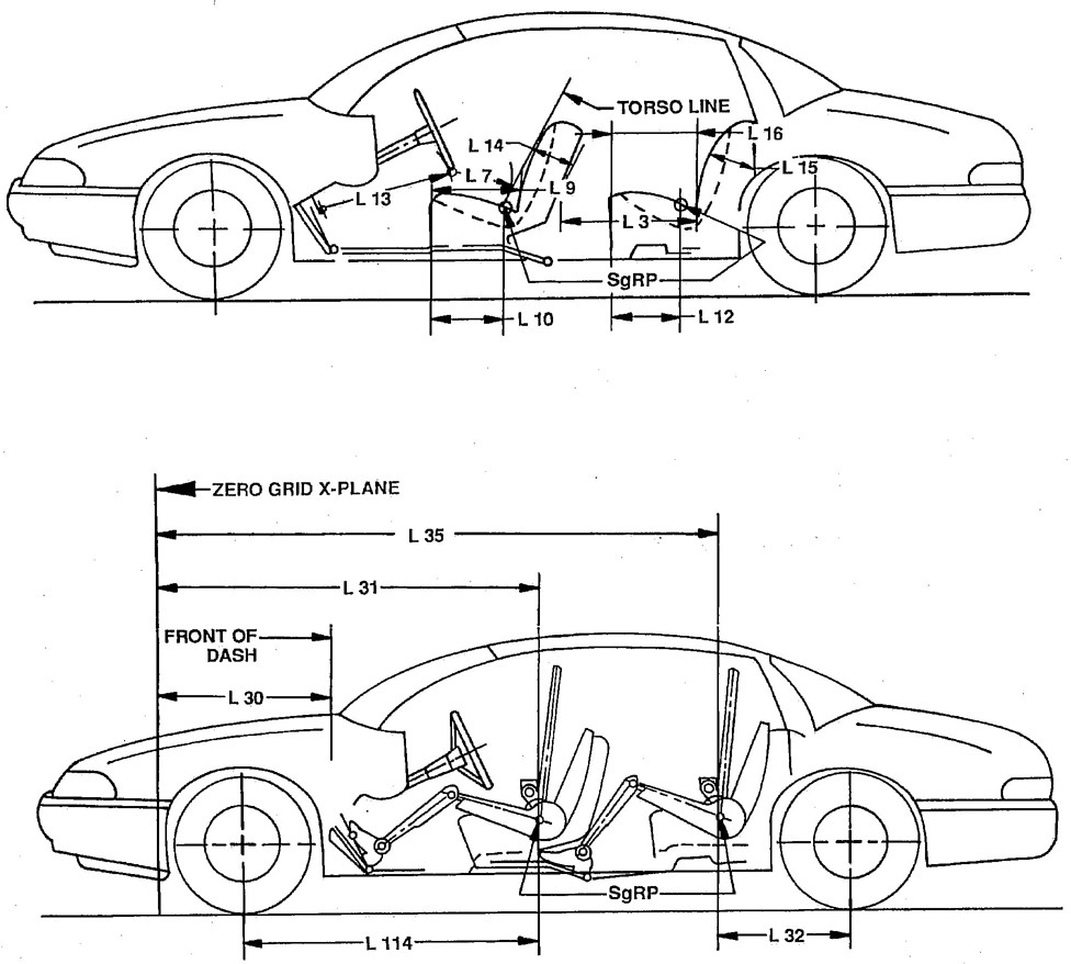
FIGURE 8—INTERIOR DIMENSIONS, LENGTH
13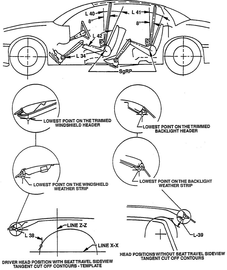
FIGURE 9—INTERIOR DIMENSIONS, LENGTH
14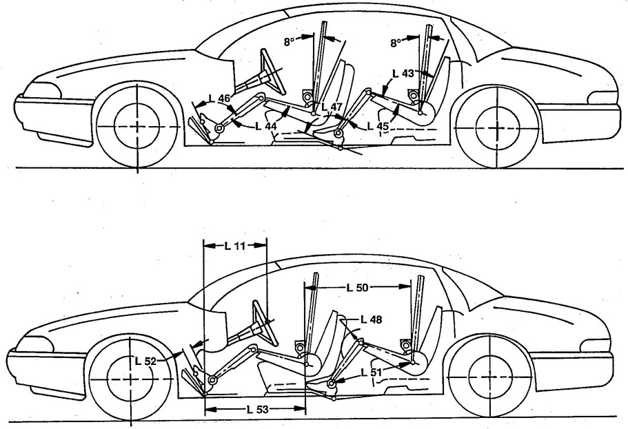
FIGURE 10—INTERIOR DIMENSIONS, LENGTH
15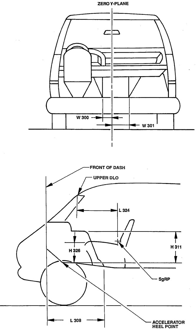
FIGURE 11—TRUCK INTERIOR DIMENSIONS, ENGINE COMPARTMENT
16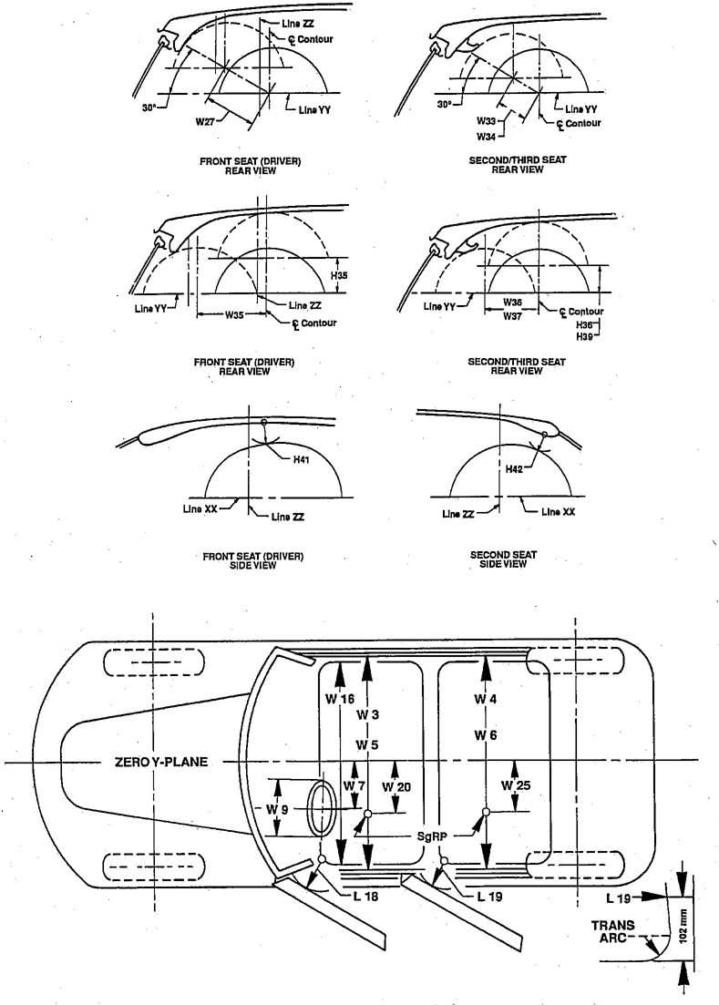
FIGURE 12—INTERIOR DIMENSIONS, WIDTH
176.1.3 H26-INTERIOR BODY HEIGHT-FRONT AT ZERO “Y” PLANE—The dimension measured along a line 8 degrees rear of vertical which lies on the zero “Y’ plane and passes through the SgRP-front “X” and “Z” coordinate from the nearest obstruction or underbody sheet metal to the roof sheet metal.
6.1.4 H27-INTERIOR BODY HEIGHT-FRONT AT SGRP “Y” PLANE—The dimension measured along a line 8 degrees rear of vertical which passes through the SgRP-front from the nearest obstruction or underbody sheet metal to the roof sheet metal.
6.1.5 H30-SGRP-FRONT TO HEEL—The dimension measured vertically from the SgRP-front to the Accelerator Heel Point.
6.1.6 #H35-VERTICAL HEAD CLEARANCE-DRIVER—The minimum vertical shift of the appropriate SAE 95th percentile rear-view head position contour until any contact is made of a section on the “X” plane intersecting the side-view top of contour. For Interference condition, move the head contour in the opposite direction and indicate a negative dimension.
6.1.7 #H37-HEADLINING TO ROOF PANEL-FRONT—The dimension from the intersection of the headlining to the sheet metal along the extended Effective Head Room line.
6.1.8 #H41-MINIMUM HEAD CLEARANCE-DRIVER—The minimum distance between the appropriate SAE 95th percentile side-view head position contour and any surface (headlining, molding, sun roof, etc.) on the “Y” plane intersecting the rear-view top of contour (centerline of contour). For interference condition, move the head contour in the opposite direction and indicate a negative dimension.
6.1.9 H53-D-POINT-FRONT TO HEEL—The vertical dimension from the D-Point to the Accelerator Heel Point.
6.1.10 H54-D-POINT-CENTER PASSENGER-FRONT TO TUNNEL—The minimum dimension measured from the D-Point-Front to the underbody sheet metal at the zero “Y” plane.
6.1.11 #H56-D-POINT-FRONT TO FLOOR—The minimum dimension measured from the D-Point-Front to the underbody sheet metal at the SgRP “Y” plane.
6.1.12 H61-EFFECTIVE HEAD ROOM-FRONT—The dimension measured along a line 8 degrees rear of vertical from the SgRP-front to the headlining, plus 102 mm (4 in).
6.1.13 H65-D-POINT-FRONT-DIFFERENTIAL, SIDE TO CENTER—The dimension measured vertically from the driver D-Point to the center occupant D-Point.
6.1.14 H67-FLOOR COVERING THICKNESS-UNDEPRESSED-FRONT—The dimension measured vertically from the surface of the Undepressed Floor Covering to the underbody sheet metal at the Accelerator Heel Point.
6.1.15 H68-FLOOR COVERING THICKNESS-DEPRESSED-FRONT—The dimension measured vertically from the Accelerator Heel Point to the underbody sheet metal.
6.1.16 H70-SGRP-FRONT “Z” COORDINATE
6.1.17 H75-EFFECTIVE T-POINT HEAD ROOM-FRONT—The minimum radius from the T-point to the headlining plus 762 mm (30 in).
6.1.18 H79-SGRP DIFFERENTIAL, SIDE TO CENTER-FRONT—The dimension measured vertically from the driver SgRP to the center occupant SgRP.
6.1.19 H311-ENGINE COVER HEIGHT—The vertical dimension from Accelerator Heel Point to top of engine cover.
186.1.20 #L27—CUSHION ANGLE—FRONT—The angle measured from a horizontal line through the SgRp-Front and the Cushion Line. The lower leg segments are detached to allow free rotation of the thigh segment around the SgRp. (See SAE J826.)
6.1.21 L31-SGRP-FRONT, “X” COORDINATE
6.1.22 L33-MAXIMUM LEG ROOM-ACCELERATOR—The dimension measured along a line from the Ankle Pivot Center to the Rearmost Design H-Point (see 14.1) plus 254 mm (10 in) measured with the right foot on the Undepressed Accelerator Pedal defined from the SgRP location. The Rearmost Highest or Rearmost Lowest Design H-Point location, or any point in between, may be used if a larger value is obtained. This assumes that the seat is not rotated and design Cushion Angle is maintained. For vehicles with SgRP to heel (H30) greater than 405 mm, the accelerator pedal may be depressed as specified by the manufacturer. If the accelerator is depressed, the manufacturer shall place foot flat on pedal and note the depression of the pedal.
6.1.23 #L34-EFFECTIVE SGRP LEG ROOM-ACCELERATOR—The dimension measured along a line from the Ankle Pivot Center to the SgRP-front plus 254 mm (10 in) measured with right foot on the Undepressed Accelerator Pedal. For vehicles with SgRP to heel (H30) greater than 405 mm, the accelerator pedal may be depressed as specified by the manufacturer. If the accelerator is depressed, the manufacturer shall place foot flat on pedal and note the depression of the pedal.
6.1.24 #L38-HEAD CLEARANCE TO WINDSHIELD GARNISH-DRIVER—The minimum distance between the appropriate SAE 95th percentile side-view head position contour and the lowest horizontal tangent point on the windshield garnish molding, weatherstrip, headlining, or header measured on the Y-plane intersecting the rear-view top of contour.
6.1.25 #L40-TORSO (BACK) ANGLE-FRONT—The angle measured between a vertical line through the SgRP-front and the Torso Line. If the seatback is adjustable, use the normal driving and riding position specified by the manufacturer.
6.1.26 L42-HIP ANGLE-FRONT—The angle measured between Torso Line and Thigh Centerline.
6.1.27 L44-KNEE ANGLE-FRONT—The angle measured between Thigh Centerline and lower leg centerline measured on the right leg.
6.1.28 L46-FOOT ANGLE-FRONT—The angle measured between the lower leg centerline and a line tangent to the ball and heel of the bare foot flesh line measured on the right leg (Reference SAE J826).
6.1.29 L53-SGRP-FRONT TO HEEL—The dimension measured horizontally from the SgRP-front to the Accelerator Heel Point.
6.1.30 L62-KNEE CLEARANCE-FRONT—The minimum dimension measured in the side-view from the Knee Pivot Center to the nearest interference minus 51 mm (2 in). The center of Knee Pivots are laterally separated for proper foot placement. The right pivot is with the right foot lined up on the accelerator and the left pivot is with the left foot on the floor in line with the clutch pedal.
6.1.31 L114-FRONT WHEEL C/L TO FRONT SGRP—The horizontal dimension measured between the Front Wheel Centerline and SgRP.
6.1.32 L308-ENGINE COVER LENGTH—The maximum dimension measured horizontally from front of dash to rear of engine cover, excluding the flanges on floor.
196.1.33 W3-SHOULDER ROOM-FRONT—The minimum dimension measured laterally between the trimmed door or quarter trim surfaces on the “X” plane through the SgRP-front at the height between the belt line and 254 mm (10 in) above the SgRP-front, excluding the door assist strap and attaching parts.
6.1.34 W5-HIP ROOM-FRONT—The minimum dimension measured laterally between the trimmed surfaces on the “X” plane through the SgRP-front within 25 mm (1 in) below, and 76 mm (3 in) above the SgRP-front and 76 mm (3 in) fore and aft of the SgRP-front. Any portion of this 101 mm by 152 mm area around the SgRP in side view below and behind the seat cushion and seat back trim is excluded. If the area is totally excluded by the seat cushion and seat back trim, measure width to trimmed door or trim surface closest, in side view, to the SgRP.
6.1.35 W20-SGRP-FRONT, “Y” COORDINATE
6.1.36 #W27-HEAD CLEARANCE DIAGONAL-DRIVER—The minimum outboard shift of the appropriate SAE 95th percentile rear-view head position contour along a line originating at the intersection of the contour centerline and a line Y-Y and at an angle of 30 degrees above horizontal while maintaining the horizontal relationship of the contour until any contact is made at a section on the “X” plane intersecting the side-view top of contour. For interference condition, move the head contour in the opposite direction and indicate a negative dimension.
6.1.37 W31 ELBOW ROOM-FRONT—The minimum dimension measured laterally between the trimmed surfaces on the “X” plane through the SgRP-front at a height 30 mm above the highest point on the flat surface of the arm rest. If no arm is provided at the designated “X” plane, use a height of 180 mm above the SgRP.
6.1.38 #W35-HEAD CLEARANCE LATERAL-DRIVER—The minimum horizontal shift of the appropriate SAE 95th percentile rear-view head position contour until any contact is made at a section on the “X” plane intersecting the side-view top of contour. For interference condition, move the head contour in the opposite direction and indicate a negative dimension.
6.1.39 #W38-HEAD CLEARANCE MINIMUM-DRIVER—The minimum distance measured between the SAE 95th percentile head position contour and the interior surface.
6.1.40 W300-ENGINE COVER WIDTH-LEFT—The maximum dimension measured laterally between the zero “Y” plane and the left side of engine cover, excluding flanges at floor.
6.1.41 W301-ENGINE COVER WIDTH-RIGHT—The maximum dimension measured laterally between the zero “Y” plane and the right side of the engine cover, excluding flanges at floor.
6.2 Second Seat Compartment Dimensions—(Left outboard passenger unless otherwise specified.) (See Figures 6, 7, 9, and 10.)
6.2.1 PD2-PASSENGER DISTRIBUTION-SECOND
6.2.2 H10-SGRP-SECOND TO GROUND—Measured in the same manner as H5.
6.2.3 H28-INTERIOR BODY HEIGHT, SECOND AT ZERO “Y” PLANE—The dimension measured along a line 8 degrees rear of vertical which lies on the zero “Y” plane and passes through the SgRP-second “X” and “Z” coordinates, from the underbody sheet metal to the roof sheet metal.
6.2.4 H29-INTERIOR BODY HEIGHT-SECOND AT SGRP “Y” PLANE—The dimension measured along a line 8 degrees rear of vertical which passes through the SgRP-second from the underbody sheet metal to the roof sheet metal.
206.2.5 H31-SGRP-SECOND TO HEEL—The dimension measured vertically from the SgRP-second to the two-dimensional device heel point on the depressed floor covering.
6.2.6 #H36-HEAD CLEARANCE VERTICAL-SECOND—The minimum vertical shift of the appropriate SAE 95th percentile rear-view head position contour until any contact is made at a section at the “X” plane intersecting the side-view top of contour. For interference condition, move the head contour in the opposite direction and indicate a negative dimension.
6.2.7 #H38-HEADLINING TO ROOF PANEL-SECOND—The dimension measured from the intersection of the headlining to the sheet metal along the extended Effective Head Room line.
6.2.8 #H42-MINIMUM HEAD CLEARANCE-SECOND—The minimum distance between the appropriate SAE 95th percentile side-view head position contour and any surface (headlining, molding, glass, etc.) on the “Y” plane intersecting the rear-view top of contour (centerline of contour). For interference condition, move the head contour in the opposite direction and indicate a negative dimension.
6.2.9 H55-D-POINT-CENTER PASSENGER-SECOND TO TUNNEL—The minimum dimension measured from the D-Point to the underbody sheet metal at the zero “Y” plane.
6.2.10 H57-D-POINT-SECOND TO FLOOR—The minimum dimension measured from the D-Point to the underbody sheet metal at the SgRP “Y” plane.
6.2.11 H60-D-POINT TO HEEL POINT-SECOND—The vertical dimension from the D-Point to Heel Point with the front seat in rearmost position.
6.2.12 H63-EFFECTIVE HEAD ROOM-SECOND—The dimension measured along a line 8 degrees rear of vertical from the SgRP to the headlining, plus 102 mm (4 in).
6.2.13 H66-D-POINT-DIFFERENTIAL, SIDE TO CENTER-SECOND—The dimension measured vertically from the D-Point to the center occupant D-Point.
6.2.14 H71-SGRP-SECOND, “Z” COORDINATE
6.2.15 H72-FLOOR COVERING THICKNESS-UNDERPRESSED-SECOND—The dimension measured vertically from the surface of the Undepressed Floor Covering to the underbody sheet metal at the heel point.
6.2.16 H73-FLOOR COVERING THICKNESS-DEPRESSED-SECOND—The dimension measured vertically from the surface of the Depressed Floor Covering to the underbody sheet metal at the heel point.
6.2.17 H76-EFFECTIVE T-POINT HEAD ROOM-SECOND—Measured in the same manner as H75.
6.2.18 #H80-SGRP-DIFFERENTIAL, SIDE TO CENTER-SECOND—The dimension measured vertically from the SgRP-second to the center occupant SgRP second.
6.2.19 L3-MINIMUM COMPARTMENT ROOM-SECOND—The minimum dimension measured horizontally from the back of the front seat to the front of the second seatback at a height tangent to the top of the second Seat Cushion within a lateral space 127 mm either side of the second seat occupant centerline. If the second seat is adjustable, it should be positioned at the SgRP and at a back angle as specified by the manufacturer.
6.2.20 L32-SGRP-SECOND TO REAR WHEEL CENTERLINE—The dimension measured horizontally from the SgRP-second to the centerline of the rear wheels.
6.2.21 L35-SGRP-SECOND, “X” COORDINATE
216.2.22 #L39-HEAD CLEARANCE TO BACKLIGHT GARNISH—The minimum distance between the appropriate SAE 95th percentile side-view head position contour and the lowest horizontal tangent point on the backlight garnish molding, weatherstrip, headlining, or header, measured on the Y-plane intersecting the rear-view top of contour.
6.2.23 #L41-TORSO (BACK) ANGLE-SECOND—The angle measured between a vertical line through the SgRP-second and the Torso Line.
6.2.24 L43-HIP ANGLE-SECOND—The angle measured between Torso Line and Thigh Centerline.
6.2.25 L45-KNEE ANGLE-SECOND—The angle measured between Thigh Centerline and lower leg centerline.
6.2.26 #L47-FOOT ANGLE-SECOND—The angle measured between the lower leg centerline and a line tangent to the ball and heel of the Three-Dimensional Devices bare foot flesh line (reference SAE J826).
6.2.27 #L48-MINIMUM KNEE CLEARANCE-SECOND—The minimum dimension within a lateral space 127 mm either side of the occupant centerline, measured from the Knee Pivot Center to the back of the front seatback, minus 51 mm (2 in). If the second seat is adjustable, it should be positioned at the SgRP and at a back angle as specified by the manufacturer.
6.2.28 L50-SGRP COUPLE DISTANCE—The dimension measured horizontally from the driver SgRP-front to the SgRP-second.
6.2.29 #L51-EFFECTIVE SGRP LEG ROOM-SECOND—The dimension measured along a line from the Ankle Pivot Center to the SgRP-second plus 254 mm (10 in). The foot may be placed on the floor pan with the centerline of the leg segment up to 127 mm either side of the Y plane occupant centerline.
6.2.30 W4-SHOULDER ROOM-SECOND—The minimum dimension measured laterally between the trimmed-door or quarter-trim surfaces on the “X” plane through the SgRP-second at a height between 254 to 406 mm (10 to 16 in) above the SgRP-second, excluding the door-assist strap and attaching parts.
6.2.31 W6-HIP ROOM-SECOND—The minimum dimension measured laterally between the trimmed surfaces on the “X” plane through the SgRP-second within 25 mm (1 in) below, and 76 mm (3 in) above the SgRP-second and 76 mm (3 in) fore and aft of the SgRP-second. Any portion of this 101 mm by 152 mm area around the SgRP in side view below and behind the seat cushion and seat back trim is excluded. If the area is totally excluded by the seat cushion and seat back trim, measure width to trimmed door or quarter trim surface closest, in side view, to the SgRP.
6.2.32 W25-SGRP-SECOND “Y” COORDINATE
6.2.33 W32-ELBOW ROOM-SECOND—The minimum dimension measured laterally between the trimmed surfaces on the “X” plane through the SgRP-second at a height 30 mm above the highest point on the flat surface of the arm rest. If no arm rest is provided at the designated “X” plane, use a height of 180 mm above the SgRP.
6.2.34 #W33-HEAD CLEARANCE DIAGONAL-SECOND—The minimum outboard shift of the appropriate SAE 95th percentile rear-view head position contour along a line originating at the intersection of the contour centerline and line Y-Y and at an angle of 30 degrees above horizontal while maintaining the horizontal relationship of the contour until any contact is made at a section on the “X” plane intersecting the side-view top of contour. For interference condition, move the head contour in the opposite direction and indicate a negative dimension.
226.2.35 #W36-HEAD CLEARANCE LATERAL-SECOND—The minimum horizontal shift of the appropriate SAE 95th percentile rear-view head position contour until any contact is made at a section on the “X” plane intersecting the side-view top of contour. For interference condition, move the head contour in the opposite direction and indicate a negative dimension.
6.2.36 #W39-HEAD CLEARANCE-MINIMUM-SECOND—The minimum distance measured between the SAE 95th percentile head position contour and the interior surface.
6.3 Truck Sleeper Compartment Dimensions—(See Figure 13.)
6.3.1 H350-SLEEPER COMPARTMENT HEIGHT—The minimum dimension from undepressed compartment overhead-trim panel to compartment floor (mattress base). This dimension shall be taken along the longitudinal centerline of the vehicle at a point 1/2 the compartment length (L350).
6.3.2 L350-SLEEPER COMPARTMENT LENGTH—The dimension of the Sleeper Compartment taken at the compartment longitudinal centerline with the soft undepressed. Dimension shall be taken from the back of the cab to the forward edge of the mattress support surface. (Truck definition: sleeper width).
6.3.3 W306-SLEEPER COMPARTMENT WIDTH—The dimension of the Sleeper Compartment taken between undepressed side-trim panels and perpendicular to the vehicle longitudinal centerline. This dimension shall be taken 305 mm (12 in) above the compartment floor (mattress base along the longitudinal centerline of the vehicle, at a point 1/2 the compartment length (L350)). (Truck definition: sleeper length.)
6.4 Third Seat Compartment Dimensions—Left outboard forward facing passenger unless otherwise specified. (See Figure 14.)
6.4.1 PD3-PASSENGER DISTRIBUTION-THIRD
6.4.2 SD1-SEAT FACING DIRECTION-THIRD
6.4.3 #H39-HEAD CLEARANCE VERTICAL-THIRD—The minimum vertical shift of the appropriate SAE 95th percentile rear-view head position contour until any contact is made at a section on the “X” plane intersecting the side-view top of contour. For interference condition, move the head contour in the opposite direction and indicate a negative dimension.
6.4.4 H62-D-POINT TO HEEL POINT-THIRD—Measured in the same manner as H60.
6.4.5 H84-HEADLINING TO ROOF-THIRD—Measured in the same manner as H38.
6.4.6 H85-SGRP-THIRD TO GROUND
6.4.7 H86-EFFECTIVE HEAD ROOM-THIRD—The dimension measured along a line 8 degrees rear of vertical from the SgRP-third to the headlining plus a constant of 102 mm (4 in).
6.4.8 H87-SGRP-THIRD TO HEEL VERTICAL
6.4.9 H88-SGRP-THIRD “Z” COORDINATE
6.4.10 H89-EFFECTIVE T-POINT HEAD ROOM-THIRD—Measured in the same manner as H75.
6.4.11 H90-D-POINT-THIRD TO FLOOR—Measured in the same manner as H57.
6.4.12 L36-SGRP-THIRD “X” COORDINATE
23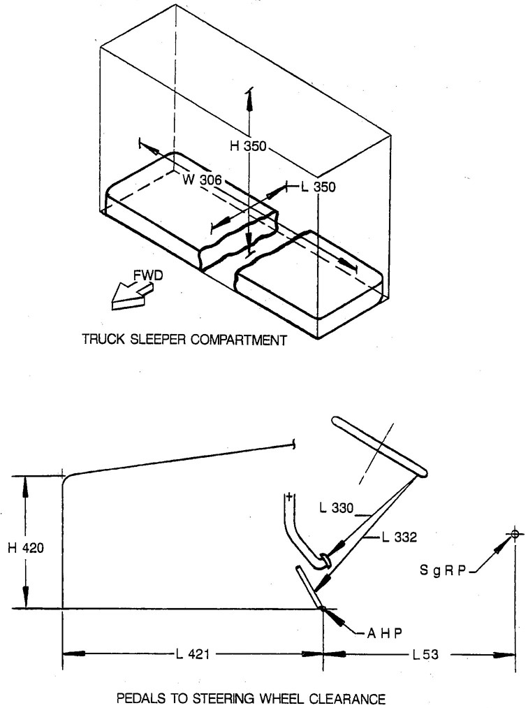
FIGURE 13—TRUCK SLEEPER COMPARTMENT AND PEDALS TO STEERING WHEEL CLEARANCE DIMENSIONS
24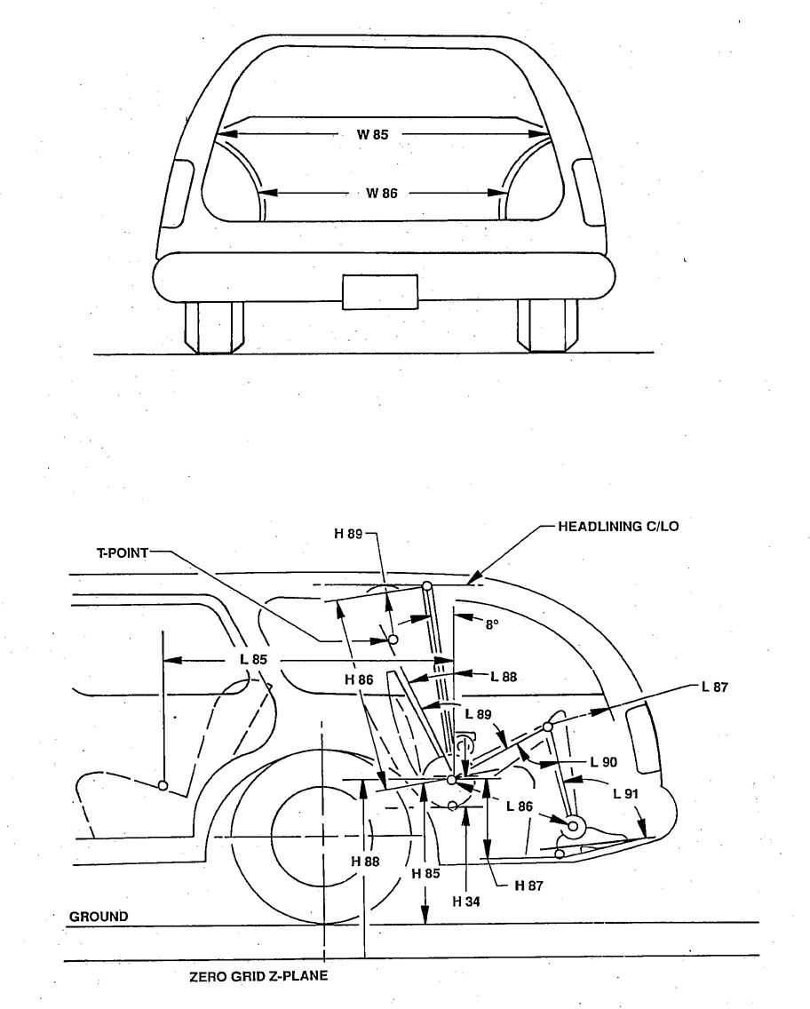
FIGURE 14—INTERIOR DIMENSIONS, STATION WAGON THIRD SEAT
256.4.13 L85-SGRP-COUPLE DISTANCE-THIRD—The dimension measured horizontally from the SgRP-second to the SgRP-third.
6.4.14 L86-EFFECTIVE SGRP LEG ROOM-THIRD—The dimension measured along a line from the Ankle Pivot Center to the SgRP-third plus 254 mm (10 in). The foot may be placed on the floor pan with the centerline of the leg segment up to 127 mm either side of the Y plane occupant centerline.
6.4.15 L87-MINIMUM KNEE CLEARANCE-THIRD—The minimum dimension within a lateral space 127 mm either side of the occupant centerline, measured from the Knee Pivot Center to the back of the second seatback, minus 51 mm (2 in). If the second and/or third seats are adjustable, they should be positioned at their respective SgRP's and at back angles as specified by the manufacturer.
6.4.16 #L88-TORSO (BACK) ANGLE-THIRD—Measured in the same manner as L41.
6.4.17 L89-HIP ANGLE-THIRD—Measured in the same manner as L43.
6.4.18 L90-KNEE ANGLE-THIRD—Measured in the same manner as L45.
6.4.19 L91-FOOT ANGLE-THIRD—Measured in the same manner as L47.
6.4.20 L92-COMPARTMENT ROOM-THIRD—The horizontal dimension from the back of the second seat to the front of the third seatback at a height tangent to the top of the third Seat Cushion. For rear-facing third seat, measure from the trimmed seat back at a height tangent to the top of the third Seat Cushion surface, rearward to the interior tailgate closure.
6.4.21 W26-SGRP-THIRD “Y” COORDINATE
6.4.22 #W34-HEAD CLEARANCE DIAGONAL-THIRD—The minimum outboard shift of the appropriate SAE 95th percentile rear-view head position contour along a line originating at the intersection of the contour centerline and line Y-Y and at an angle of 30 degrees above horizontal while maintaining the horizontal relationship of the contour until and contact is made at a section on the “X” plane intersecting the side-view top of contour. For interference condition, move the head contour in the opposite direction and indicate a negative dimension.
6.4.23 #W37-HEAD CLEARANCE LATERAL-THIRD—The minimum horizontal shift of the appropriate SAE 95th percentile rear-view head position contour until any contact is made at a section on the “X” plane intersecting the side-view top of contour. For interference condition, move the head contour in the opposite direction and indicate a negative dimension.
6.4.24 #W40-HEAD CLEARANCE MINIMUM-THIRD—The minimum distance measured between the SAE 95th percentile head position contour and the vehicle interior.
6.4.25 W43-ELBOW ROOM-THIRD—The minimum dimension measured laterally between the trimmed surfaces on the “X” plane through the SgRP-third at a height 30 mm above the highest point on the flat surface of the arm rest. If no arm rest is provided at the designated “X” plane, use a height of 180 mm above the SgRP.
6.4.26 W85-SHOULDER ROOM-THIRD—Measured in the same manner as W4.
6.4.27 W86-HIP ROOM-THIRD—The minimum dimension measured laterally between the trimmed surfaces on the “X” plane through the SgRP-third within 25 mm (1 in) below, and 76 mm (3 in) above the SgRP-third and 76 mm (3 in) fore and aft of the SgRP-third. Any portion of this 101 mm by 152 mm area around the SgRP in side view below and behind the seat cushion and seat back trim is excluded. If the area is totally excluded by the seat cushion and seat back trim, measure width to trimmed door or quarter trim surface closest, in side view, to the SgRP.
266.5 Seat, Entrance and Exit Dimensions—(See Figures 4 through 7, 12, 15, 16.)
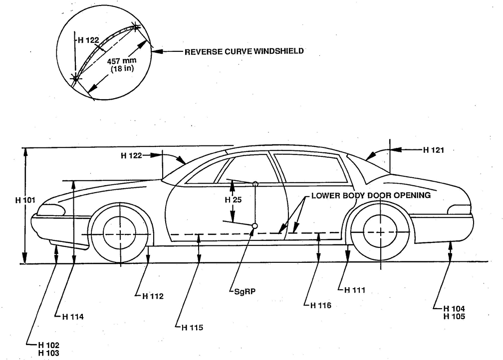
FIGURE 15—EXTERIOR DIMENSIONS, HEIGHT
27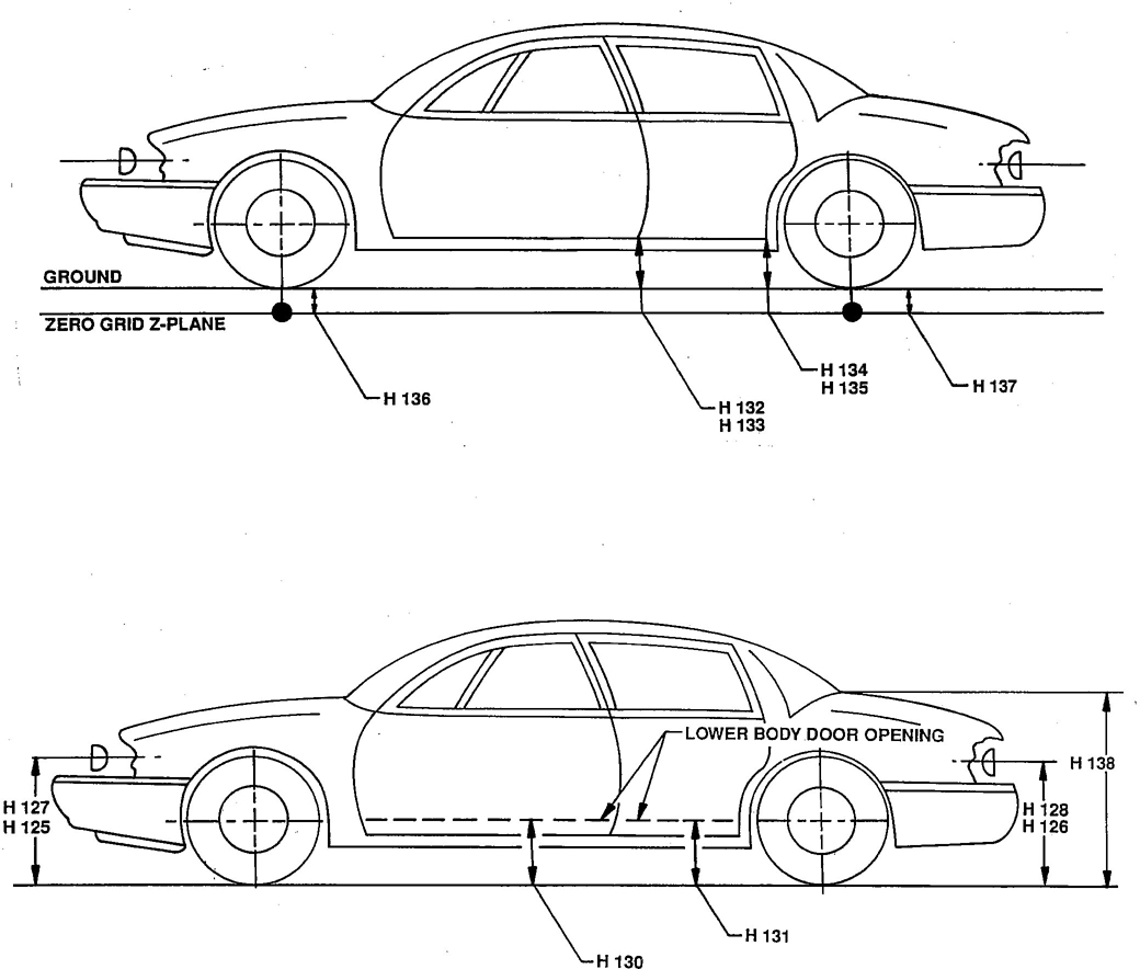
FIGURE 16—EXTERIOR DIMENSIONS, HEIGHT
6.5.1 H11-ENTRANCE HEIGHT-FRONT—The dimension measured vertically from the SgRP-front “X” plane to the upper trimmed body opening at SgRP station.
6.5.2 H12-ENTRANCE HEIGHT-SECOND—The dimension measured vertically from the SgRP-second to the upper trimmed body opening at a section 330 mm (13 in) forward of the SgRP.
6.5.3 H32-CUSHION DEFLECTION-FRONT—The dimension measured vertically from the free to the depressed Front Seat Cushion (see SAE J826) on the SgRP-front “Y” plane.
6.5.4 H33-CUSHION DEFLECTION-SECOND—The dimension measured vertically from the free to the depressed Second Seat Cushion (see SAE J826) on the SgRP-second “Y” plane.
286.5.5 H34-CUSHION DEFLECTION-THIRD—The dimension measured vertically from the free to the depressed Third Seat Cushion (see SAE J826) on the SgRP-third “Y” plane.
6.5.6 H40-STEERING WHEEL TO ACCELERATOR HEEL POINT—The minimum vertical dimension measured from the lowest edge of the Steering Wheel, in the straight-ahead position, to the Accelerator Heel Point.
6.5.7 H50-UPPER-BODY OPENING TO GROUND-FRONT—The dimension measured vertically from the trimmed body opening to the ground on the SgRP-front “X” plane.
6.5.8 H51-UPPER-BODY OPENING TO GROUND-SECOND—The dimension measured vertically from the trimmed body opening to the ground on the “X” plane 330 mm (13 in) forward of the SgRP-second.
6.5.9 H69-EXIT HEIGHT-SECOND—The dimension measured vertically from the SgRP-second to the upper trimmed body opening 254 mm (10 in) forward of the intersection of the trimmed body opening and a horizontal plane 483 mm (19 in) above the SgRP-second seat.
6.5.10 H74-STEERING WHEEL TO CUSHION—The minimum dimension measured between the steering wheel, with the front wheels in straight-ahead position, and the undepressed Seat Cushion on the Steering Wheel Center “Y” Plane.
6.5.11 H77-SEATBACK HEIGHT-FRONT—A dimension measured along the Torso Line from the SgRP-front to a line normal to the Torso Line and tangent to the top of the seatback soft trim or head restraint in the stowed position.
6.5.12 #H78-SEATBACK HEIGHT-SECOND—A dimension measured along the Torso Line from the SgRP-second seat to a line normal to the Torso Line and tangent to the top of the seatback soft trim or head restraint in the stowed position.
6.5.13 #H92-SEATBACK HEIGHT-THIRD—A dimension measured along the Torso Line from the SgRP-third seat to a line normal to the Torso Line and tangent to the top of the seatback soft trim or head restraint in the stowed position.
6.5.14 H94-STEERING WHEEL TO CUSHION-MINIMUM—The minimum dimension measured between the Steering Wheel, with the Steering Wheel turned to its lower position, and the undepressed Seat Cushion on the Steering Wheel Center “Y” plane.
6.5.15 H115-STEP HEIGHT-FRONT—The dimension will be to the top of the sill plate bead at the center of the lower door opening. If there is a step, the dimension is measured vertically from the ground to the first step entering the vehicle.
6.5.16 H116-STEP HEIGHT-SECOND—The dimension will be to the top of the sill plate at the center of the lower door opening. If there is a step, the dimension is measured vertically from the ground to the first step entering the vehicle.
6.5.17 H130-STEP HEIGHT-FRONT (CURB WEIGHT)—The dimension will be to the top of the sill plate at the center of the lower door opening. If there is a step, the dimension is measured vertically from the ground to the first step entering the vehicle.
6.5.18 H131-STEP HEIGHT-SECOND (CURB WEIGHT)—The dimension will be to the top of the sill plate bead at the center of the lower door opening. If there is a step, the dimension is measured vertically from the ground to the first step entering the vehicle.
296.5.19 H326-SEAT CUSHION HEIGHT-FRONT—The vertical dimension from the point of intersection of the horizontal tangent to the top of the Seat Cushion and the vertical tangent to the front of the Seat Cushion, to Accelerator Heel Point.
6.5.20 H445-SECOND STEP HEIGHT-FRONT—The vertical dimension from the first step entering vehicle to Second Step. If there is no second step, the dimension will be to the top of the sill plate bead at the center of the lower door opening.
6.5.21 H446-SECOND STEP HEIGHT-SECOND—The vertical dimension from the first step entering vehicle to second step. If there is no second step, the dimension will be to the top of the sill plate bead at the center of the lower door opening.
6.5.22 L9-CUSHION DEPTH-FRONT—The dimension measured horizontally from the front edge of the cushion to an “X” plane tangent to the undepressed seatback at a height tangent to the top of the Seat Cushion.
6.5.23 L10-EFFECTIVE CUSHION DEPTH-FRONT—The dimension measured horizontally from the front edge of the cushion to the SgRP.
6.5.24 L12-EFFECTIVE CUSHION DEPTH-SECOND—The dimension measured horizontally from the front edge of the cushion to the SgRP.
6.5.25 L14-SEATBACK THICKNESS-FRONT—The maximum dimension measured through the front seatback, excluding bolsters.
6.5.26 L15-SEATBACK THICKNESS-SECOND—The maximum dimension measured through the second seatback, excluding bolsters.
6.5.27 L16-CUSHION DEPTH-SECOND—The dimension measured horizontally from the front edge of the cushion to an “X” plane tangent to the undepressed seatback at a height tangent to the top of the Seat Cushion.
6.5.28 L18-ENTRANCE FOOT CLEARANCE-FRONT—The minimum dimension measured horizontally between the trimmed front Seat Cushion frame or supporting structure and the trimmed door or pillar at a height between the sill plate bead and 102 mm (4 in) above the bead with the door in the maximum hold-open position.
6.5.29 L19-ENTRANCE FOOT CLEARANCE-SECOND
6.5.30 L20-SEATBACK THICKNESS-THIRD—The maximum dimension measured through the third seatback excluding bolsters.
6.5.31 #L21-CUSHION DEPTH-THIRD—The dimension measured horizontally from the front edge of the cushion to an “X” plane tangent to the undepressed seatback at a height tangent to the top of the Seat Cushion.
6.5.32 L22-STEERING WHEEL TO SEATBACK—The minimum distance measured between the steering wheel, in its straight-ahead position and the undepressed seatback on the Steering Wheel center “Y” plane.
6.5.33 L24-EFFECTIVE CUSHION DEPTH-THIRD—The dimension measured horizontally from the front edge of the cushion to the SgRP.
306.5.34 W16-CUSHION WIDTH-FRONT—The maximum dimension measured laterally across the trimmed width of the front Seat Cushion.
6.6 Vision and Control Dimensions—Driver unless otherwise specified. (See Figures 5, 12, 13, and 15.)
6.6.1 #H6-SGRP-FRONT TO WINDSHIELD LOWER DLO—The dimension measured vertically from the SgRP-front the windshield lower DLO at C/LO.
6.6.2 H13-STEERING WHEEL TO CENTERLINE OF THIGH—The minimum dimension measured from the bottom of steering wheel, with front wheels in the straight-ahead position, to the Thigh Centerline.
6.6.3 H14-EYELLIPSE TO BOTTOM OF INSIDE REARVIEW MIRROR—The dimension measured vertically from a horizontal plane tangent to the top of the SAE 95th percentile Eyellipse to the Bottom Edge of Rearview Mirror frame in the lowest usable position of adjustment. A minus (−) dimension indicates the mirror is located below the horizontal plane. (If the mirror is located on the instrument panel, the dimension will be measured from the top of the mirror frame in the highest usable position to the bottom of SAE 95th percentile eyellipse.)
6.6.4 H17-ACCELERATOR HEEL POINT TO THE STEERING WHEEL CENTER—The dimension measured vertically from the AHP-front to the intersection of the steering column centerline with a plane tangent to the upper surface of the Steering Wheel rim.
NOTE—The steering column center is used instead of the wheel center to eliminate error that could occur with a non-symmetrical Steering Wheel.
6.6.5 H18-STEERING WHEEL ANGLE—The angle measured from a vertical to the surface plane of the Steering Wheel.
6.6.6 H25-BELT HEIGHT-FRONT—The dimension measured vertically from the SgRP-front to the bottom of the side window DLO at SgRP “X” plane.
6.6.7 H49-EYELLIPSE TO TOP OF STEERING WHEEL—The dimension measured vertically from a horizontal plane tangent to the bottom of the SAE 95th percentile Eyellipse to the Top of the Steering Wheel, in the straight-ahead position. A minus (−) dimension indicates the bottom of the eyellipse is located below the top of the steering wheel.
6.6.8 #H64-SGRP-FRONT TO WINDSHIELD UPPER DLO—The dimension measured vertically from the SgRP-front to the windshield upper DLO at C/L of driver.
6.6.9 #H121-BACKLIGHT SLOPE ANGLE—The angle between a vertical reference line at the vehicle zero “Y” plane and a 457 mm (18 in) chord of the backlight arc running from the deck point to the intersecting point on the exterior backlight glazing surface. Measure the same as H122.
6.6.10 #H122-WINDSHIELD SLOPE ANGLE—The angle between a vertical reference line at the vehicle zero “Y” plane and a 457 mm (18 in) chord of the windshield arc running from the Cowl Point to the intersecting point on the exterior windshield glazing surface.
6.6.11 H123-EYELLIPSE TO BACKLIGHT UPPER OPENING—The vertical distance from a horizontal plane tangent to the top of the SAE 95th percentile eyellipse to the highest horizontal line of vision through the backlight upper trimmed body opening at zero “Y” plane.
6.6.12 H124-VISION ANGLE TO WINDSHIELD UPPER DLO—The angle from the horizontal to a plane tangent to the top of the SAE 95th percentile eyellipse and to the upper trimmed body opening measured at C/LO.
316.6.13 #H129-WINDSHIELD SLOPE-DRIVER VISION—(Class A Vehicles only) (The angle from vertical to a line defined by two sightline intersection points on the exterior windshield glazing surface. These sightlines are drawn from the 95% eyellipse (see SAE J941) in the X/Z plane through the “Y” centerline of driver. The upward angle sightline is at 7 degrees tangent to the upper portion of the eyellipse while the downward angle sightline is at 5 degrees tangent to the lower portion of the eyellipse.
6.6.14 H420-DISTANCE FROM AHP TO INTERSECTION OF FRONT AND TOP SURFACE OF HOOD
6.6.15 L6-BALL OFF FOOT TO STEERING WHEEL CENTER—The dimension measured horizontally from the BOF to the intersection of the steering wheel centerline and a plane tangent to the face of the steering wheel rim.
6.6.16 L7-STEERING WHEEL TORSO CLEARANCE—The minimum dimension measured in the side-view from the rearmost edge of the Steering Wheel with front wheels in the straight-ahead position, to the Torso Line.
6.6.17 L11-ACCELERATOR HEEL POINT TO STEERING WHEEL CENTER—The dimension measured horizontally from the AHP to the intersection of the steering wheel centerline and a plane tangent to the face of the steering wheel rim.
6.6.18 #L13-BRAKE PEDAL KNEE CLEARANCE—See Section 13 - Pedal Dimensions.
6.6.19 #L52-BRAKE PEDAL TO ACCELERATOR—See Section 13 - Pedal Dimensions.
6.6.20 #L324-SGRP TO WINDSHIELD UPPER DLO—The horizontal dimension from the SgRP to the point of tangency of a horizontal line to upper DLO at C/L of driver.
6.6.21 L330-CLUTCH PEDAL TO STEERING WHEEL CLEARANCE—The minimum dimension in side-view from the lower edge of the Steering Wheel rim to the centerline of the clutch pedal face with pedal in the free or undepressed position.
6.6.22 L332-ACCELERATOR PEDAL TO STEERING WHEEL CLEARANCE—The minimum dimension in side-view from the lower edge of the Steering Wheel rim to a point on the pedal surface 203 mm from the Accelerator Heel Point with pedal in the free or undepressed position.
6.6.23 L421-MAXIMUM DISTANCE FROM AHP TO INTERSECTION OF FRONT AND TOP SURFACE OF HOOD
6.6.24 W7-STEERING WHEEL CENTER “Y” COORDINATE—The Steering Wheel Center is the point located by the intersection of the steering column axis with the plane tangent to the upper surface of the Steering Wheel rim.
6.6.25 W9-STEERING WHEEL MAXIMUM OUTSIDE DIAMETER—Maximum width across the steering wheel face outside of rim to outside of rim in rear view (X plane).
6.6.26 W30-STEERING WHEEL TO DOOR CLEARANCE—The minimum dimension from the Steering Wheel rim to the nearest body obstruction. Specify location.
6.6.27 W41-SIDE GLASS RADIUS—Specify location.
6.6.28 W122-TUMBLE-HOME
7. Exterior Dimensions
7.1 Exterior Width Dimensions—(See Figures 17 and 18.)
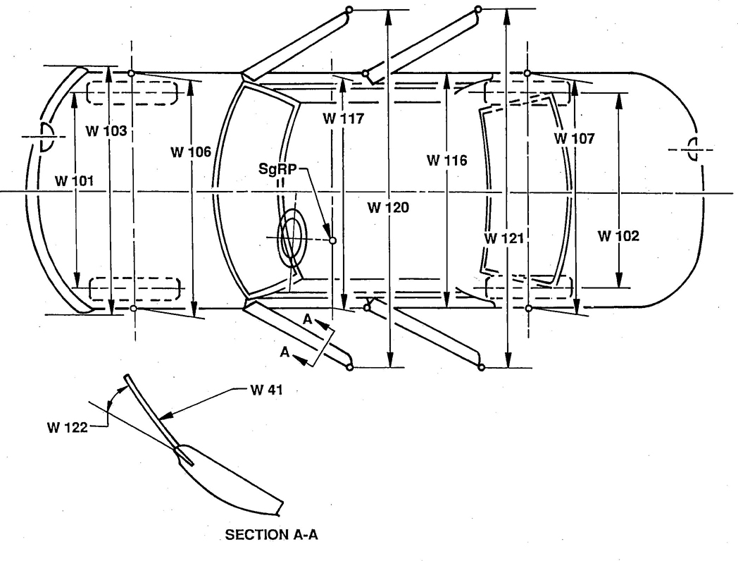
FIGURE 17—EXTERIOR DIMENSIONS, WIDTH
33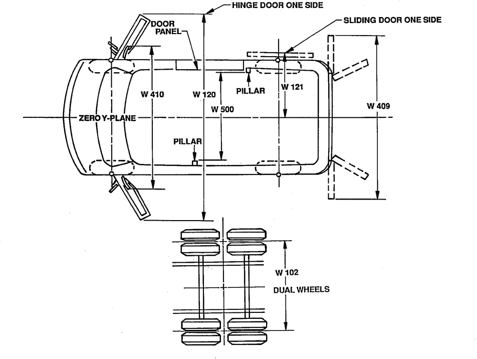
FIGURE 18—TRUCK EXTERIOR DIMENSIONS, WIDTH
7.1.1 W101-TREAD-FRONT—The dimension measured between the tire centerlines at the ground.
7.1.2 W102-TREAD-REAR—The dimension measured between the tire centerlines at the ground. In case of dual wheels, the dimension will be measured to the centerline of tire and wheel assemblies.
7.1.3 #W103-VEHICLE WIDTH—The maximum dimension measured between the widest points on the vehicle, excluding exterior mirrors, flexible mud flaps, and marker lamps, but including bumpers, moldings, sheet metal protrusions, or dual wheels, if standard equipment.
7.1.4 W106-FRONT FENDER WIDTH—The dimension measured between the widest points at the front wheel centerline, excluding moldings.
7.1.5 W107-REAR FENDER WIDTH—The dimension measured between the widest points at the rear wheel centerline, excluding moldings.
7.1.6 #W116-BODY WIDTH-MAXIMUM—The dimension measured between the widest points on the body, excluding mirrors, hardware, and applied moldings, but including fenders when integral with body.
347.1.7 #W117-BODY WIDTH AT SGRP-FRONT—The dimension measured laterally between the widest points on the body at the SgRP-front, excluding door handles, applied moldings, and appliques.
7.1.8 #W120-VEHICLE WIDTH-FRONT DOORS OPEN—The dimension measured between the widest points on the front doors in maximum hold-open position.
7.1.9 #W121-VEHICLE WIDTH-REAR DOORS OPEN—The dimension measured between the widest points on the rear doors in maximum hold-open position. For vehicles with a rear door on only one side, this dimension is to the zero “Y” plane.
7.1.10 W409-VEHICLE WIDTH-TAIL DOORS OPEN—The dimension measured between the widest point on the tail doors in the maximum hold-open position.
7.1.11 #W410-VEHICLE WIDTH-INCLUDING OUTSIDE MIRRORS—The dimension measured between the widest points on the outside mirrors. The standard right and left mirror adjusted for normal driving will be shown unless otherwise noted. When only one outside mirror is standard, the dimension will be to the zero “Y” plane.
7.2 Exterior Height Dimensions—(See Figures 15, 16, 19, and 20.)
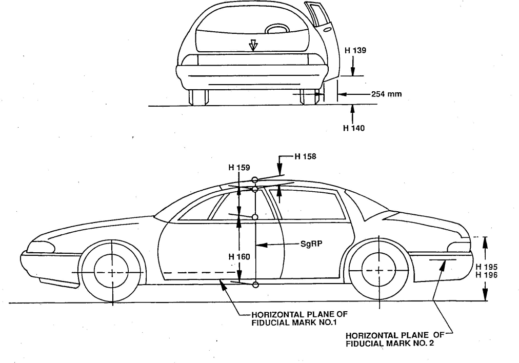
FIGURE 19—EXTERIOR DIMENSIONS, HEIGHT
35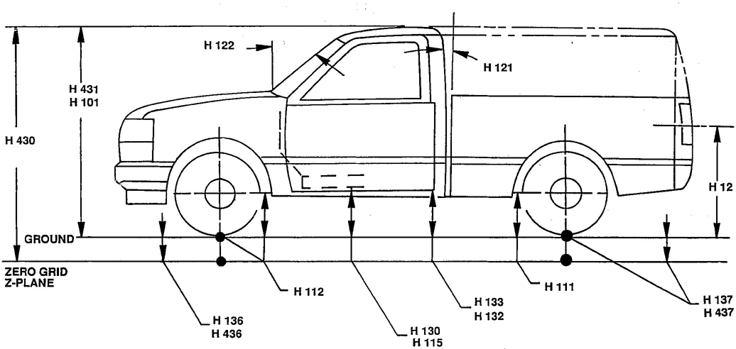
FIGURE 20—TRUCK EXTERIOR DIMENSIONS, HEIGHT
7.2.1 H101-VEHICLE HEIGHT—The dimension measured vertically from the highest point on the vehicle body to ground.
7.2.2 H111-ROCKER PANEL-REAR TO GROUND—The dimension measured vertically from the bottom of the rocker or side-quarter panel at the front of the rear wheel opening, excluding flanges, to ground.
7.2.3 H112-ROCKER PANEL-FRONT TO GROUND—The dimension measured vertically from the foremost point on the bottom of the Rocker Panel, excluding flanges, to ground.
7.2.4 H114-COWL POINT TO GROUND—The dimension measured from the Cowl Point to Ground at the zero “Y” plane.
7.2.5 H125-HEADLAMP TO GROUND—The dimension measured vertically from the centerline of the lowest Headlamp lens to Ground.
7.2.6 H126-TAILLAMP TO GROUND—The dimension measured vertically from the centerline of the upper bulb to ground.
7.2.7 H127-HEADLAMP TO GROUND-CURB WEIGHT—The dimension measured vertically from the centerline of the lowest Headlamp lens to Ground.
7.2.8 H128-TAILLAMP TO GROUND-CURB WEIGHT—The dimension measured vertically from the centerline of the upper bulb to ground.
7.2.9 H132-BOTTOM OF DOOR OPEN-FRONT TO GROUND—The dimension vertically from the bottom outside corner of the door on the lock pillar side, in maximum hold-open position to ground.
367.2.10 H133-BOTTOM OF DOOR CLOSED-FRONT TO GROUND—The dimension measured vertically from the bottom outside corner of the door on the lock pillar side, closed position, to ground.
7.2.11 H134-BOTTOM OF DOOR OPEN-REAR TO GROUND—The dimension measured vertically from the bottom outside corner of the door on the lock pillar side, in maximum hold-open position, to ground.
7.2.12 H135-BOTTOM OF DOOR CLOSED-REAR TO GROUND—The dimension measured vertically from the bottom outside corner of the door on the lock pillar side, closed position, to ground.
7.2.13 H136-ZERO “Z” PLANE TO GROUND-FRONT—The dimension measured vertically at front wheel centerline to ground.
7.2.14 H137-ZERO “Z” PLANE TO GROUND-REAR—The dimension vertically at rear wheel centerline to ground. In the case of dual rear axles, the dimension will be taken at centerline between the rear wheels.
7.2.15 H138-DECK POINT TO GROUND—Measured at zero “Y” plane.
7.2.16 H139-BOTTOM OF DOOR AJAR, FRONT TO GROUND—The dimension measured vertically from the bottom outside corner of the door on the lock pillar side, open 254 mm (10 in) to the ground.
7.2.17 H140-BOTTOM OF DOOR AJAR-REAR TO GROUND—The dimension measured vertically from the bottom outside corner of the door on the lock pillar side, open 254 mm (10 in) to ground.
7.2.18 H158-ROOF THICKNESS—The dimension measured vertically from the top of the roof to the upper DLO at the 1270 mm (50 in), ‘X’ plane SgRP station, or less, if DLO obscured.
7.2.19 H159-SIDE GLASS HEIGHT—The dimension measured vertically between the upper and lower DLO at the 1270 mm (50 in), ‘X’ plane SgRP station or less, if DLO obscured.
7.2.20 H160-BODY THICKNESS—The dimension measured vertically from the lower DLO to the bottom of the Rocker Panel, excluding any flanges, at the 1270 mm (50 in), ‘X’ plane SgRP station, or less, unless otherwise specified.
7.2.21 H195-LIFTOVER HEIGHT—The dimension measured vertically from the Luggage Compartment lower opening at the zero ‘Y’ plane to ground.
7.2.22 H196-LIFTOVER HEIGHT-CURB WEIGHT—The dimension measured vertically from the Luggage Compartment lower opening at the zero ‘Y’ plane to ground.
7.2.23 H404-MAXIMUM OVERALL HEIGHT-TILT CAB SERVICING—The vertical dimension from the highest point on the cab to ground, including exhaust outlet or other attached components, measured at the point of maximum height during tilting of the cab.
7.2.24 H430-BODY HEIGHT—The “Z” coordinate of highest point of roof.
7.2.25 H431-VEHICLE HEIGHT (CURB WEIGHT)—The dimension measured vertically from the highest point on the vehicle body to ground.
7.2.26 H436-ZERO “Z” PLANE TO GROUND-FRONT (CURB WEIGHT)—The dimension measured vertically at front wheel centerline to ground.
7.2.27 H437-ZERO “Z” PLANE TO GROUND-REAR (CURB WEIGHT)—The dimension measured vertically at rear wheel centerline to ground. In the case of dual rear axles, the dimension will be taken at centerline between the rear wheels.
377.3 Exterior Length Dimensions—(See Figures 3, 21, and 22.)
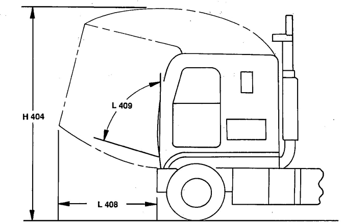
FIGURE 21—CAB SERVICING DIMENSIONS
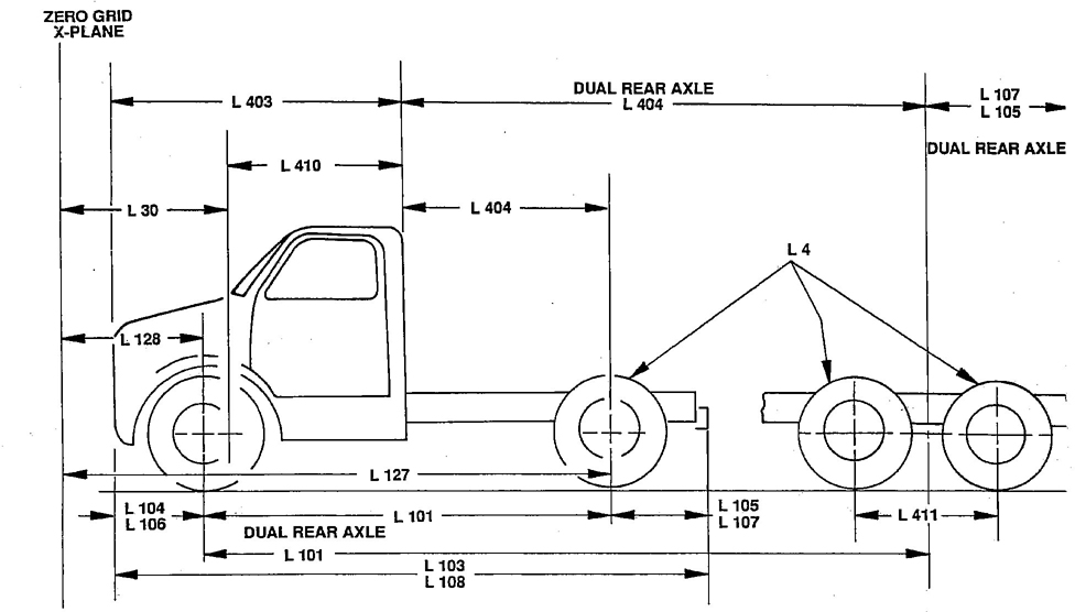
FIGURE 22—TRUCK EXTERIOR DIMENSIONS, LENGTH
387.3.1 L30-FRONT OF DASH “X” COORDINATE—A minus (-) dimension indicates actual front of dash is forward of the zero “X” plane.
7.3.2 L101-WHEELBASE (WB)—The dimension measured longitudinally between front and rear wheel centerlines. In case of dual rear axles, the dimension shall be to the midpoint of the centerlines of the rear wheels.
7.3.3 L103-VEHICLE LENGTH—The maximum dimension measured longitudinally between the foremost point and the rearmost point on the vehicle, including bumper, bumper guards, tow hooks, and/or rub strips, if standard equipment.
7.3.4 L104-OVERHANG-FRONT—The dimension measured longitudinally from the centerline of the front wheels to the foremost point on the vehicle, including bumper, bumper guards, tow hooks, and/or rub strips, if standard equipment.
7.3.5 L105-OVERHANG-REAR—The dimension measured longitudinally from the centerline of the rear wheels; or in the case of dual rear axles, the dimension shall be from the midpoint of the centerlines of the rear wheels, to the rearmost point on the vehicle, including rear bumpers, bumper guards, tow hooks, and rubstrips, if standard equipment.
7.3.6 L106-OVERHANG-FRONT-RPO—This dimension is measured the same as L104, except all RPO items are included.
7.3.7 L107-OVERHANG-REAR-RPO—This dimension is measured the same as L105, except all RPO items are included.
7.3.8 L108-VEHICLE LENGTH-RPO—This dimension is measured the same as L103, except all RPO items are included.
7.3.9 L123-UPPER STRUCTURE LENGTH—The dimension measured longitudinally from the Cowl Point to the deck point.
7.3.10 L125-COWL POINT “X” COORDINATE
7.3.11 L126-FRONT END LENGTH—The dimension measured longitudinally from the Cowl Point to the foremost point on the vehicle at the zero “Y” plane, excluding ornamentation or bumpers. In cases where bumpers and/or grills are integrated with the profile, measurement is made at the foremost point of front end contour.
7.3.12 L127-REAR WHEEL CENTERLINE—“X” Coordinate or in the case of dual rear axles, the coordinate shall be the midpoint of the distance between the rear axle centerlines.
7.3.13 L128-FRONT WHEEL CENTERLINE “X” COORDINATE
7.3.14 L129-REAR END LENGTH—The dimension measured longitudinally from the deck point to the rearmost visible point of the body sheetmetal at the zero “Y” plane, excluding ornamentation or bumpers.
7.3.15 L403-FRONT OF BUMPER TO BACK OF CAB (BBC)—A horizontal dimension from the front of the front bumper to the back of cab at zero “Y” plane.
7.3.16 L404-CAB TO REAR AXLE (CA)—A horizontal dimension from the rear axles, the dimension shall be to their midpoint.
7.3.17 L408-FRONT BUMPER TO CAB-TILT CAB SERVICING POSITION—The horizontal dimension from the front of bumper to the foremost point of the cab, measured with the cab in the maximum servicing tilt position.
397.3.18 L409-CAB SERVICING TILT ANGLE—The maximum angle of cab tilt for servicing, measured from a vertical line.
7.3.19 L410-CAB LENGTH—A longitudinal dimension from front of dash to back of cab at zero “Y” plane.
7.3.20 L411-DUAL REAR AXLE SPACING—Horizontal dimension from centerline of forward rear axle to centerline of rearward rear axle at the zero “Y” plane.
7.4 Ground Clearance Dimensions—(See Figure 23.)
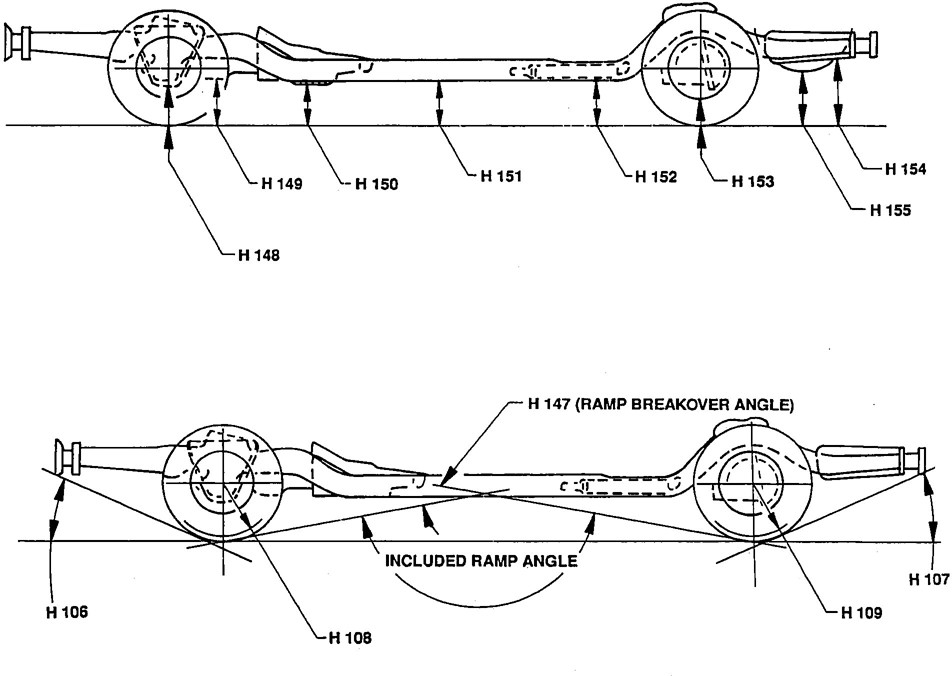
FIGURE 23—GROUND CLEARANCE DIMENSIONS
7.4.1 H102-FRONT BUMPER TO GROUND—The minimum dimension measured vertically from the lowest point on the front bumper to ground, including bumper guards, if standard equipment.
7.4.2 H103-FRONT BUMPER TO GROUND-CURB WEIGHT—Measured in the same manner as H102.
7.4.3 H104-REAR BUMPER TO GROUND—The minimum dimension measured vertically from the lowest point on the Rear Bumper to Ground, including bumper guards, if standard equipment.
7.4.4 H105-REAR BUMPER TO GROUND-CURB WEIGHT—Measured in the same manner as H104.
407.4.5 H106-ANGLE OF APPROACH—The angle measured between a line tangent to the front tire static-loaded radius are and the initial point of structural interference forward of the front tire to ground. The limiting structural component shall be designated.
7.4.6 H107-ANGLE OF DEPARTURE—The angle measured between a line tangent of the rear tire static-loaded radius are and the initial point of structural interference rearward of the rear tire to ground. The limiting component shall be designated.
7.4.7 H108-STATIC LOAD-TIRE RADIUS-FRONT—Specified by the manufacturer in accordance with Composite Tire Section Standard.
7.4.8 H109-STATIC LOAD-TIRE RADIUS-REAR—Specified by the manufacturer in accordance with Composite Tire Section Standard.
7.4.9 H147-RAMP BREAKOVER ANGLE—The angle measured between two lines tangent to the front and rear tire static loaded radius and intersecting at a point on the underside of the vehicle which defines the largest ramp over which the vehicle can roll.
7.4.10 H148-FRONT SUSPENSION TO GROUND—The minimum dimension measured from the Front Suspension to ground. Specify component.
7.4.11 #H149-OIL PAN TO GROUND—The minimum dimension measured from Oil Pan or drain plug to ground.
7.4.12 H150-FLYWHEEL/CONVERTER HOUSING AND TRANSMISSION ASSEMBLY TO GROUND—The minimum dimension measured from Flywheel/Converter Housing transfer case and/or Transmission Assembly to ground.
7.4.13 H151-FRAME STRUCTURE TO GROUND—The minimum dimension measured approximately midway between front and rear axles including cross bars and x-members to ground.
7.4.14 H152-EXHAUST SYSTEM TO GROUND—The minimum dimension measured from the Exhaust System to Ground. Specify location.
7.4.15 H153-REAR AXLE DIFFERENTIAL TO GROUND—The minimum dimension measured from the Rear Axle Differential to ground.
7.4.16 #H154-FUEL TANK TO GROUND—The minimum dimension measured from Fuel Tank or drain plug, including supports or straps to ground.
7.4.17 H155-SPARE TIRE WELL TO GROUND—The minimum dimension measured from the Spare Tire Well or Spare Tire including supports, to ground.
7.4.18 H156-MINIMUM RUNNING GROUND CLEARANCE—The minimum dimension measured from the sprung vehicle to ground. Specify location.
7.4.19 L102-TIRE SIZE—As specified by the manufacturer.
7.4.20 L4-TIRE SIZE-REAR ONLY IF DIFFERENT THAN FRONT—As specified by manufacturer.
418. Cargo Dimensions—(See Figures 24 through 28.)
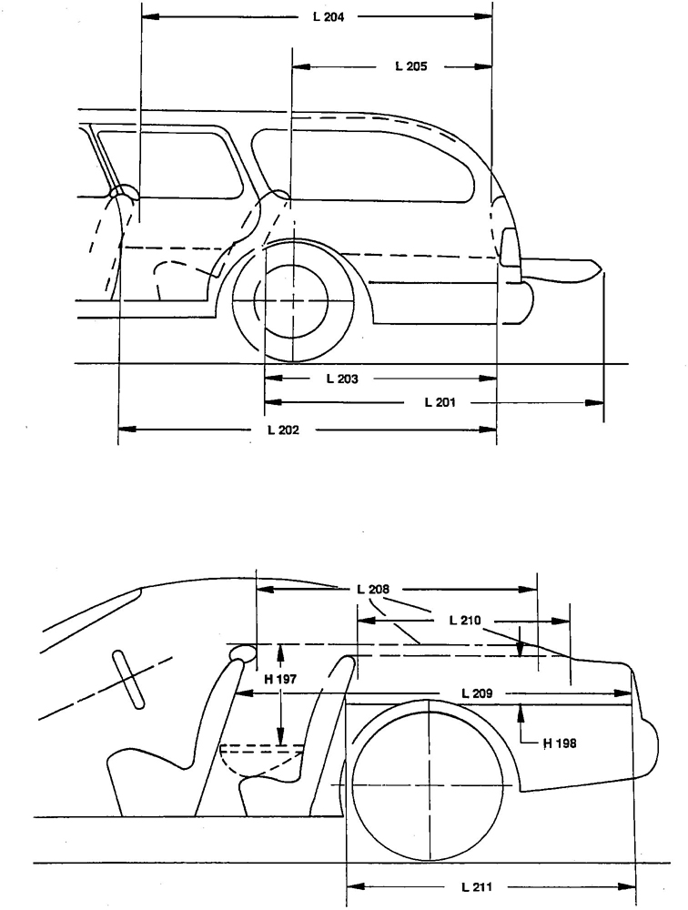
FIGURE 24—CARGO SPACE DIMENSIONS
42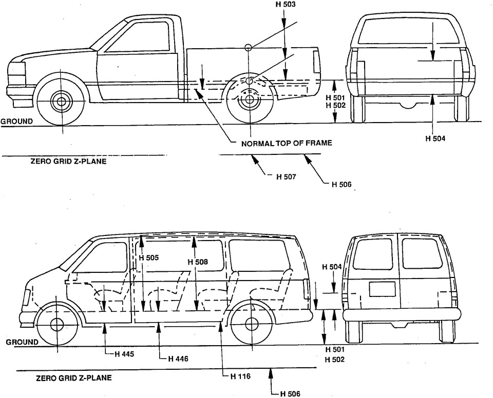
FIGURE 25—TRUCK-CARGO SPACE DIMENSIONS, HEIGHT
43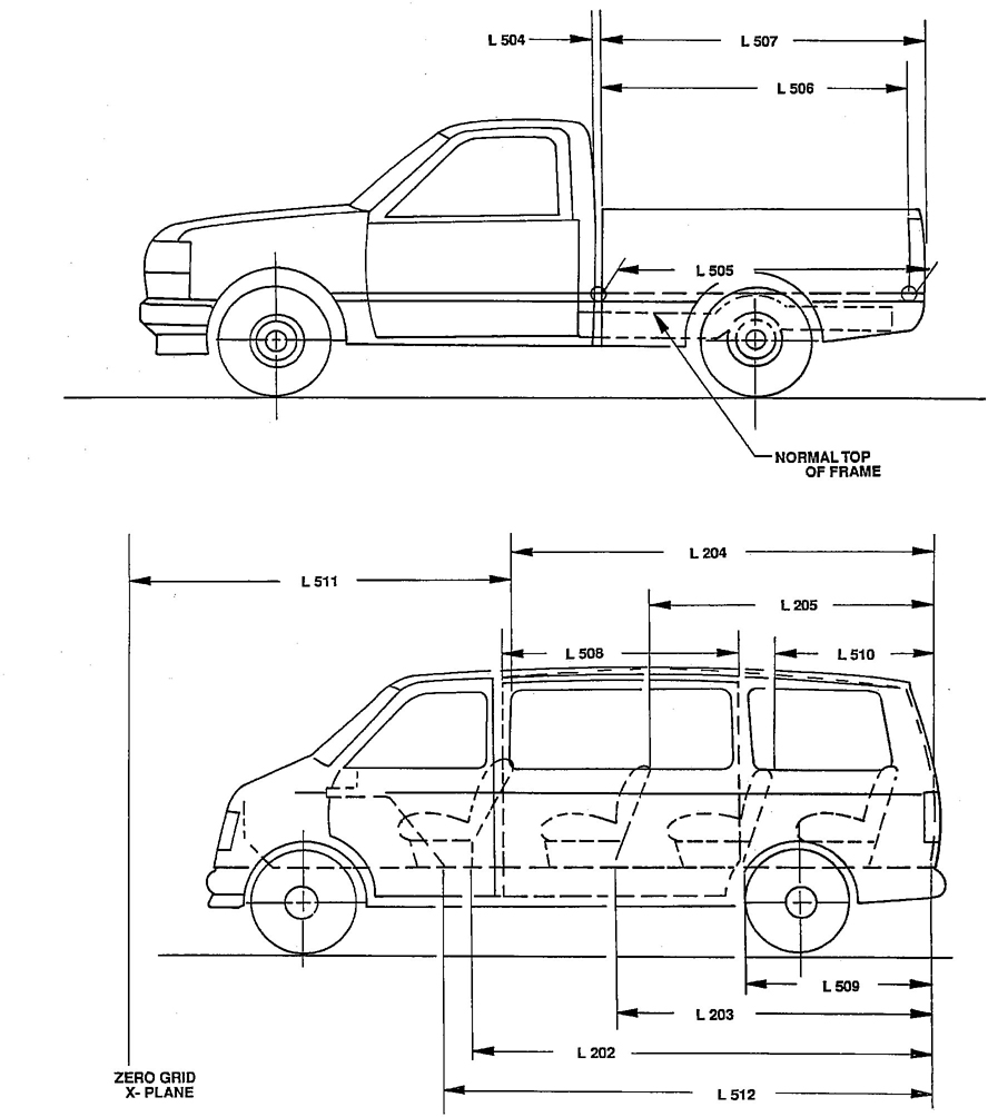
FIGURE 26—TRUCK CARGO SPACE DIMENSIONS, LENGTH
44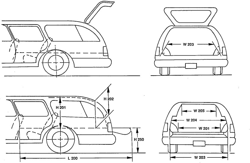
FIGURE 27—CARGO SPACE DIMENSIONS
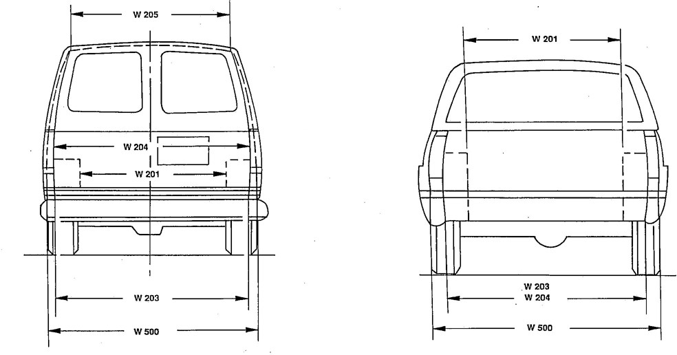
FIGURE 28—TRUCK-CARGO SPACE DIMENSIONS, WIDTH
458.1H197-Seatback to Load Floor Height-Front——The dimension measured vertically from the horizontal tangent to the top of the front seatback including headrests to the Undepressed Floor Covering.
8.2 #H198-Seatback to Load Floor Height-Second— The dimension measured vertically from the top of the second seatback including headrests to the Undepressed Floor Covering.
8.3 #H199-Seatback to Load Floor Height-Third— The dimension measured vertically from the top of the third seatback including headrests to the Undepressed Floor Covering.
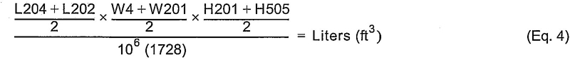
8.4 H201-Cargo Height— The dimension measured vertically from the top of the Undepressed Floor Covering to the headlining at the rear wheel “X” coordinate on the zero “Y” plane.
8.5 H202-Rear Opening Height— The dimension measured vertically from the top of the Undepressed Floor Covering to the upper trimmed opening on the zero “Y” plane with rear door fully open.
8.6 H250-Tailgate to Ground (Curb Weight)— The dimension measured vertically from the top of the Undepressed Floor Covering on the lowered tailgate to ground on the zero “Y” plane.
8.7 H501-Cargo Floor Height to Ground— A vertical dimension from the Cargo Floor intersection with closed rear tailgate or cargo door to ground.
8.8 H502-Cargo Floor Height to Ground (Curb Weight)— A vertical dimension from the Cargo Floor intersection with closed rear tailgate or cargo door to ground.
8.9 H503-Pickup Body Height— The minimum dimension measured vertically from the top of Cargo Floor to the top of the pickup at the rear wheel “X” coordinate.
8.10 H504-Wheelhouse Height— The maximum vertical dimension from top of Cargo Floor to the top of rear wheelhouse.
8.11 H505-Maximum Cargo Height— The maximum vertical dimension rear of the front seat from the Cargo Floor to roof bow or headlining at the zero “Y” plane.
8.12 H506-Cargo Floor Height— The “Z” coordinate of the top of Cargo Floor.
8.13 H507-Frame Height— The “Z” coordinate of normal top of frame.
8.14 H508-Side Cargo Door Opening Height— The dimension measured vertically from the top of the Undepressed Floor Covering or Cargo Floor to the upper side trimmed opening with side Cargo Doors open.
8.15 L200-Cargo Length-Open-Front—The minimum dimension measured longitudinally from the back of the front seatback at the height of the Undepressed Floor Covering to the rearmost point on the Undepressed Floor Covering on the open tailgate or cargo surface, if the rear closure is a conventional door type tailgate, at the zero “Y” plane.
8.16 L201-Cargo Length-Open-Second— The dimension measured longitudinally from the back of the second seatback at the height of the Undepressed Floor Covering to the rearmost point on the Undepressed Floor Covering on the open tailgate or Cargo Floor surface, if the rear closure is a conventional door type tailgate, at the zero “Y” plane.
8.17 L202-Cargo Length-Closed-Front— The minimum dimension measured horizontally from the back of the front seat at the height of the Undepressed Floor Covering to the rearmost point on the Undepressed Floor Covering on the closed tailgate or tail door for station wagons, trucks, and MPV's at the zero “Y” plane.
468.18 L203-Cargo Length-Closed-Second— The minimum dimension measured horizontally from the back of the second seat at the height of the Undepressed Floor Covering to the rearmost point on the Undepressed Floor Covering on the closed tailgate or taildoor for station wagons, trucks, and MPV's at the zero “Y” plane.
8.19 L204-Cargo Length at Belt-Front— The minimum dimension measured horizontally from the back of the front seatback at the seatback top to the foremost normal surface of the closed tailgate or inside surface of the cab back panel at the height of the belt, on the zero “Y” plane.
8.20 L205-Cargo Length at Belt-Second— The minimum dimension measured horizontally from the back of the second seatback at the seatback top to the foremost normal surface of the closed tailgate at the height of the belt, on the zero “Y” plane.
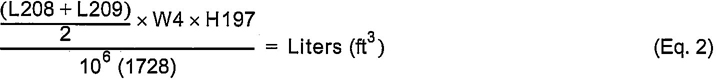
8.21 L208-Cargo Length at Front Seatback Height-Hatchback—The minimum horizontal dimension from the “X” plane tangent to the rearmost surface of the driver's seatback to the inside limiting interference of the hatchback door on the vehicle zero “Y” plane.
8.22 L209-Cargo Length at Floor-Front-Hatchback— The minimum horizontal dimension measured at floor level from the rear of the front seatback to the normal limiting interference of the hatchback door on the vehicle zero “Y” plane.
8.23 L210-Cargo Length at Second Seatback-Hatchback—The minimum horizontal dimension measured from the “X” plane that is tangent to the rearmost surface of the second seatback to an “X” plane that is tangent to the rearmost inside limiting interference on the zero “Y” plane at a height tangent to the top of the seatback including headrest.
8.24 L211-Cargo Length at Floor-Second-Hatchback—The minimum horizontal dimension measured at floor level from the rear of the second seatback or load floor panel to the normal limiting interference of the hatchback door on the vehicle zero “Y” plane.
8.25 L504-Cab to Pickup Body— The horizontal dimension from rear of cab to the front of the Pickup Body, measured at the zero “Y” plane.
8.26 L505-Pickup Body Length at Floor— The dimension measured longitudinally from inside front of Pickup Body to the inside top of the closed tailgate measured at floor level at the zero “Y” plane.
8.27 L506-Pickup Body Length at Top of Body— The dimension measured longitudinally from inside front of Pickup Body to the inside top of the closed tailgate measured at top of the Pickup Body at the zero “Y” plane.
8.28 L507-Cargo Body Overall Length— A longitudinal dimension of the Overall Cargo Body Length at the zero “Y” plane.
8.29 L508-Side Cargo Door Opening Length— The minimum dimension measured longitudinally between the limiting interferences with Side Cargo Doors in maximum hold-open position.
8.30 L509-Cargo Length-Closed-Third— The minimum dimension measured horizontally from the back of the third seat (including seat support and restraint system) at the height of the Undepressed Floor Covering to the rearmost point on the Undepressed Floor Covering on the closed tailgate or taildoor at the zero “Y” plane. For vehicles with more than three seats, specify seat location along with dimension.
8.31 L510-Cargo Length at Belt-Third— The minimum dimension measured horizontally from the back of the third seat back to the foremost normal surface of the closed tailgate or taildoor at the height of the belt on zero “Y” plane. For vehicle with more than three seats, specify seat location along with dimension.
478.32 L511-Front Cargo Surface— The “X” coordinate of the front cargo surface. This surface is the rearmost point of driver's seat on trucks with closed cargo area and is the front surface of the inside of cargo box on trucks with open cargo area.
8.33 L512-Cargo Length to Engine Cover— The dimension measured longitudinally for the rear of the engine cover to the closed tailgate or taildoor at the zero “Y” plane. The dimension shall be at height of the cargo floor surface. If floor surface at engine cover is above cargo floor surface, then length is taken at floor to engine cover intersection height.
8.34 W201-Cargo Width-Wheelhouse— The minimum dimension measured laterally between the trimmed wheelhousings at floor level. For any vehicle not trimmed, measure the sheet metal.
8.35 W203-Rear Opening Width at Floor— The minimum dimension measured laterally between the limiting interferences of the Rear Opening at Floor level.
8.36 W204-Rear Opening Width at Belt— The minimum dimension measured laterally between the limiting interferences of the Rear Opening at Belt height or top of pickup box.
8.37 W205-Rear Opening Width Above Belt— The minimum dimension measured laterally between the limiting interferences of the Rear Opening Above the Belt height. See also Figures 27 and 28.
8.38 W500-Cargo Width at Floor— The maximum dimension measured laterally between the limiting vertical trimmed surfaces near the floor level. This dimension excludes wheelhouses, local protrusions, and local depressions or pockets.
9. Luggage Capacity— (Passenger car enclosed Luggage Compartments including hatchbacks and station wagons partitioned to secure hidden cargo)
V1-Luggage Capacity
Total of volumes of individual pieces of standard luggage set plus H-boxes stowed in the Luggage Compartment in accordance with the procedure described in 9.2.
9.1 Standard Luggage Set— The Standard Luggage Set consists of a set of replicas of luggage and golf bags (see Figure 29) with contents. A set of shoe-type boxes (H-boxes) are optionally used with the Standard Luggage Set. Descriptions and sizes of the luggage pieces are detailed in Table 1.
9.2 Procedure For Determining Usable Luggage Capacity— Place in random order as many as one Standard Luggage Set of Luggage into the Luggage Compartment, excluding H boxes. When the best load is obtained using the Standard Luggage Set, H-boxes may be added to arrive at the final load. Pieces from subsequent Standard Luggage Sets may be used when the previous set is placed in the Luggage Compartment. A piece from the Standard Luggage Set may be removed to place an H-box in the compartment, provided the removed piece is replaced. The standard equipped spare tire and tools shall be properly installed in the Luggage Compartment. They may be loosened and moved to the limits of the attaching hardware and then retightened to attain the most advantageous position. Standard parts of the vehicle normally stored in the Luggage Compartment, such as a convertible top, shall be in the stored position when the usable Luggage Capacity is determined. The Luggage Compartment Lid or access door must close and lock freely without forcing or excessive slamming with all of the luggage in place in the compartment.
48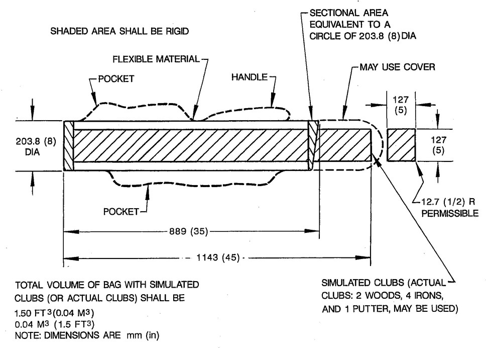
FIGURE 29—GOLF BAG
| Luggage (with conventional handles) |
Box Size mm |
Box Size in |
Letter | No. | Volume/Piece m3 |
Volume/Piece ft3 |
|---|---|---|---|---|---|---|
| Men's 2-suiter | 229×483×610 | 9×19×24 | A | 4 | 0.067 | 2.375 |
| Women's overnight | 165×330×457 | 6.5×13×18 | B | 4 | 0.025 | 0.880 |
| Women's pullman | 229×406×660 | 9×16×26 | C | 2 | 0.061 | 2.167 |
| Women's wardrobe | 216×457×533 | 8.5×18×21 | D | 2 | 0.053 | 1.859 |
| Women's train case | 203×229×381 | 8×9×15 | E | 2 | 0.018 | 0.625 |
| Men's overnight | 178×356×533 | 7×14×21 | F | 2 | 0.034 | 1.191 |
| Golf bag containing: 2 woods, 4 irons, 1 putter, size 10-1/2 shoes, 3 golf balls |
See Figure 29 | G | 2 | 0.043 | 1.500 | |
| H-boxes | 152×114×325 | 6×4.5×12.8 | H | 20 | 0.006 | 0.200 |
| Total | 38 |
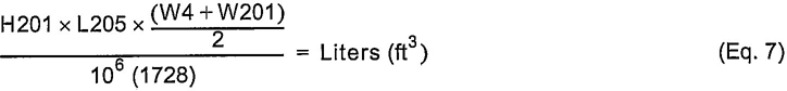
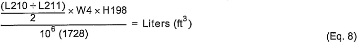
10. Cargo Volume Index— Input values are mm (inches). Use appropriate value in denominator for metric (English) units.
10.1 V2 - Station Wagon Cargo Volume Index-Maximum

10.2 #V3 - Hatchback Cargo Volume Index-Maximum
10.3 V4 - Hidden Luggage Capacity-Rear of Front Seat— The total volumes of individual pieces of one set of Standard Luggage stowed in any hidden cargo are below the load floor Rear of the Front Seat.
10.4 V5 - Open Trucks and MPV Cargo Volume Index-Maximum

10.5 V6 - Enclosed Truck and MPV Cargo Volume Index-Maximum Behind Front Seat
NOTE—Use W500 if W4 if not defined.
10.6 #V7 - Enclosed Truck and MPV Cargo Volume Index-Maximum Behind Second Seat
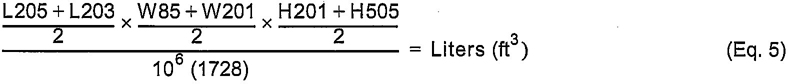
NOTE—Use W500 if W85 is not defined.
10.7 #V9 - Enclosed Truck and MPV Cargo Volume Index-Maximum Behind Third Seat
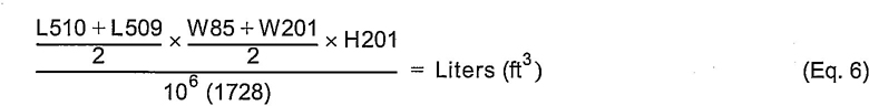
50NOTE—Use W500 if W85 is not defined.
10.8 V10 - Station Wagon Cargo Volume Index-Maximum, Behind Second Seat
10.9 V11 - Hatchback Cargo Volume index-Maximum Behind Second Seat
11. ISO Cargo Volumes— The following Volume Dimensions employ the International Standards Organization (ISO) method of Cargo Volume measurement. They are included in an effort to harmonize world-wide vehicle dimensioning practices and to permit accurate comparison of domestic and off-shore vehicle dimensions.
11.1 ISO Cargo Volume Modules— Rectangular parallel piped with rounded edges of maximum radius 10 mm and of the volume specified in Table 2.
Larger unit modules may be constructed to facilitate measuring oversized spaces provided that the length, width, and height of the modules are dimensionally equivalent (including tolerances) to a stack of Type A and/ or Type B unit modules.
| Style | Length (mm) | Width (mm) | Height (mm) | Volume |
|---|---|---|---|---|
| Type A | 400 | 200 | 100 | 8 cu. dm. |
| Type B | 200 | 100 | 50 | 1 cu. dm. |
11.2 Procedure for Determining Luggage Capacity— Place in random order as many of either type of module into the Luggage Compartment as will fit. The standard equipped spare tire and tools shall be properly installed. They may be loosened and moved to the limits of the attaching hardware and then retightened to attain the most advantageous position. Standard parts of the vehicle normally installed in the Luggage Compartment such as a convertible top shall be in the stored position when the Luggage Capacity is determined. The Luggage Compartment Lid or access door must close and lock freely without forcing or excessive slamming with all of the cargo modules in place in the compartment.
11.2.1 ISO V210-ENCLOSED LUGGAGE COMPARTMENT VOLUME—Total volumes of individual cargo volume modules stowed in the Enclosed Luggage Compartment of a passenger car (including hatchbacks and station wagons partitioned to secure hidden cargo) in accordance with the procedure described in 11.2.
11.2.2 ISO V211-OPEN LUGGAGE COMPARTMENT VOLUME—BEHIND THE SECOND SEAT—The total volumes of individual cargo volume modules stowed in accordance with 11.2 below a line parallel to the main load floor and tangent to the upper edge of the second seatback (excluding headrests). Any seats aft of the second seat may be folded and/or removed according to the manufacturer's instructions in order to enlarge the luggage compartment. The forward limit is the rear side of the second seatback or the folded third seat.
11.2.3 ISO V212-OPEN LUGGAGE COMPARTMENT–BEHIND THE FIRST SEAT—The total volumes of individual cargo volume modules stowed in accordance with 11.2 below a line parallel to the main load floor and tangent to the upper edge of the first seatback (excluding headrests). Rear seats may be folded and/or removed according to the manufacturer's instructions in order to enlarge the luggage compartment. The forward limit is the rear side of the front seatback, and/or the folded second seat.
5111.2.4 ISO V213-OPEN LUGGAGE COMPARTMENT—BEHIND THE THIRD SEAT—The total volumes of individual cargo volume modules stowed in accordance with 11.2 below a line parallel to the main load floor and tangent to the upper edge of the third seatback (excluding headrests). Any seats aft of the third seat may be folded and/or removed according to the manufacturer's instructions in order to enlarge the luggage compartment. The forward limit is the rear side of third seatback and/or the folded fourth seat.
11.2.5 ISO V214-LARGEST LUGGAGE VOLUME—The total volumes of individual cargo volume modules stowed in accordance with 11.2 such that the load height is limited by the headlining. The forward limit is the rear side of rear of the front seatback, and a vertical plane tangent to and extending above the front seatback. Rear seats may be folded and/or removed according to the manufacturer's instructions in order to enlarge the luggage compartment.
12. Glass Areas
S1 - Windshield Area
S2 - Side Windows Area. Includes the front door, rear door, vents, and rear-quarter windows on both sides of the vehicle.
S3 - Backlight Areas
S4 - Total Areas. Total of all areas. (S1 + S2 + S3)
13. Pedals
13.1 Pedal Dimension Definitions—Pedal dimensions are established in two views: a side-view and a true view on the Accelerator Foot Plane in relation to the Ball of Foot (BOF) and Accelerator Heel Point (AHP). The prefix “P” is added to the L (length). W (width) and H (height) codes to denote specific pedal dimensions. Reference points for pedal dimensions are as follows:
13.1.1 Y-PLANE (SIDE-VIEW)—Ball of Foot on the Accelerator Foot Plane and Accelerator Heel Point.
13.1.2 ACCELERATOR FOOT PLANE (REAR-VIEW)—SgRP front Y coordinate (W20) and zero Y coordinate of vehicle.
13.1.3 Ball of Foot (BOF), Accelerator Heel Point (AHP), and Accelerator Foot Plane (AFP) are defined in 3.16.
13.2 Pedal Dimensions—(See Figures 30 to 32.)
13.2.1 L13-BRAKE PEDAL KNEE CLEARANCE—The minimum dimension measured in the side-view from the lower edge of the steering wheel rim to the centerline of the brake pedal face with pedals in the free position.
13.2.2 L52-BRAKE PEDAL TO ACCELERATOR—The minimum dimension measured in the side-view from the center of the brake pedal face to the accelerator pedal face with pedals in free position. A minus (–) dimension indicates that the brake pedal is lower than the accelerator pedal.
13.2.3 PL1-ACCELERATOR TO BRAKE LIFTOFF—Perpendicular distance between the Accelerator Foot Plane and a parallel plane tangent to the undepressed brake pedal pad.
13.2.4 PL2-BRAKE TO CLUTCH LIFTOFF—The perpendicular distance between two planes, parallel to the Accelerator Foot Plane, one tangent to the brake pedal pad and the other tangent to the clutch pedal pad. If the clutch is forward of the brake, the dimension is negative.
13.2.5 PW1-CLUTCH PEDAL WIDTH—Maximum width of the clutch pedal pad viewed normal to the Accelerator Foot Plane.
13.2.6 PW2-BRAKE PEDAL WIDTH—Maximum width of automatic or manual brake pedal pad viewed normal to the Accelerator Foot Plane.
52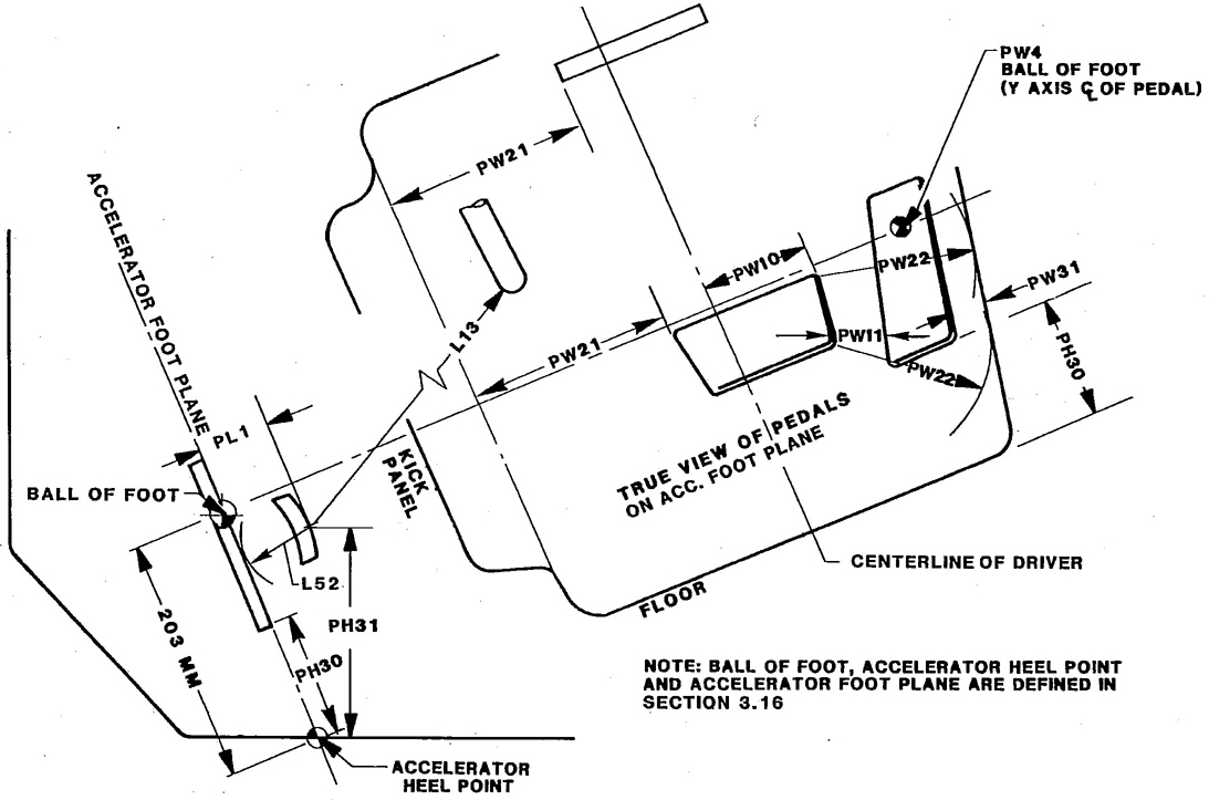
FIGURE 30—PEDAL POSITION MEASUREMENTS—AUTOMATIC TRANSMISSION
53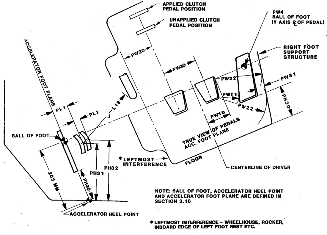
FIGURE 31—PEDAL POSITION MEASUREMENTS—MANUAL TRANSMISSION VEHICLES
54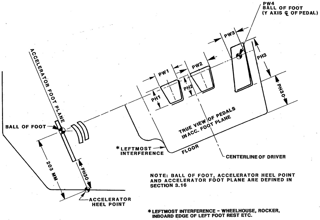
FIGURE 32—PEDAL SHAPES AND SIZES—MANUAL AND AUTOMATIC TRANSMISSION VEHICLES
5513.2.7 PW3-ACCELERATOR PEDAL PAD WIDTH—Lateral distance measured through the Ball of Foot reference point parallel to the Y-axis.
13.2.8 PW4-‘Y’ COORDINATE AT CENTERLINE OF ACCELERATOR PEDAL PAD—Measured at ball of foot height.
13.2.9 PW10-RIGHT EDGE OF BRAKE PEDAL TO CENTERLINE OF DRIVER—SgRP front Y coordinate to the right-most edge of the brake pedal pad. This is a negative dimension if the brake pedal is left of the centerline of driver.
13.2.10 PW11-ACCELERATOR TO BRAKE LATERAL SEPARATION—Minimum distance measured between the right edge of the brake pedal pad and the left edge of the accelerator pedal viewed normal to the Accelerator Foot Plane.
13.2.11 PW20-CLUTCH PEDAL FOOT CLEARANCE—Minimum distance measured between the centerline of the clutch pedal pad and the right edge of the nearest interference (wheelhouse, left foot rest, rocker, etc.) throughout the clutch pedal travel.
13.2.12 PW21-LEFT FOOT SPACE—Minimum distance between the left-most edge of the undepressed brake pedal pad (automatic transmission) and the right edge of the nearest interference (wheelhouse, rocker, inboard edge of left foot rest) through the stroke of the pedal.
13.2.13 PW22-LATERAL SPACE FOR ACCELERATOR PEDAL OPERATION—Minimum distance measured between the right foot support structure at the Accelerator Foot Plane and the right edge of the brake pedal pad viewed normal to the Accelerator Foot Plane.
13.2.14 PW30-BRAKE TO CLUTCH LATERAL SEPARATION—Minimum distance measured between the center of the manual brake pedal pad and the center of the clutch pedal pad viewed normal to the Accelerator Foot Plane.
13.2.15 PW31-ACCELERATOR PEDAL TO RIGHT FOOT SUPPORT STRUCTURE—Minimum distance measured from the right edge of the Accelerator Pedal to the Right Foot Support Structure (tunnel or console) at the Accelerator Foot Plane.
13.2.16 PH1-CLUTCH PEDAL PAD HEIGHT—Maximum height of the Clutch Pedal Pad viewed normal to the Accelerator Foot Plane.
13.2.17 PH2-BRAKE PEDAL PAD HEIGHT—Maximum height of the brake pedal viewed normal to the Accelerator Foot Plane.
13.2.18 PH3-ACCELERATOR PEDAL HEIGHT—Maximum height of the Accelerator Pedal viewed normal to the Accelerator Foot Plane.
13.2.19 PH30-BOTTOM OF ACCELERATOR PEDAL TO FLOOR—Minimum distance from the Accelerator Heel Point to the Bottom of the Accelerator Pedal viewed normal to the Accelerator Foot Plane.
13.2.20 PH31-CENTERLINE OF BRAKE PEDAL TO FLOOR—Vertical distance from the brake pedal at the center of the pedal pad surface to the floor at the Accelerator Heel Point.
13.2.21 PH32-CENTERLINE OF CLUTCH PEDAL TO FLOOR—Vertical distance from the clutch pedal at the center of the pedal pad surface to the floor covering.
5614. Design H-Point Travel Path
14.1 Design H-Point Travel Path Definitions—H-Point travel path for the driver's seat is established in side-view relative to the SgRP. See H70, L31, and W20. The prefix T is added to the L (length) and H (height) to denote specific H-Point travel path dimensions. TL and TH dimensions from 2 through 5 apply only when vertical adjustment is provided independent of track rise with forward movement. Track rise, when provided, is the amount the H-Point increases in height with forward movement due to an inclined seat track.
Reference points defining H-Point travel path are as follows:
14.2 Design H-Point Travel Path Dimensions—(See Figure 33.)
14.2.1 TL2-SGRP TO REARMOST-LOWEST DESIGN H-POINT—The dimension measured horizontally from the SgRP to the rearmost location at full down Design H-Point. This measurement accounts for adjustments independent of track rise.
14.2.2 TH2-SGRP TO REARMOST-LOWEST DESIGN H-POINT—The dimension measured vertically from the SgRP to the rearmost location at full down Design H-Point. This measurement includes vertical adjustment independent of track rise.
14.2.3 TL3-SGRP TO FOREMOST-LOWEST DESIGN H-POINT—The dimension measured horizontally from the SgRP to the foremost location at full down Design H-Point. The dimension is negative if the SgRP is below the Foremost-Lowest Design H-Point. This measurement accounts for adjustments independent of track rise.
14.2.4 TH3-SGRP TO FOREMOST-LOWEST DESIGN H-POINT—The dimension measured vertically from the SgRP to the foremost location at full down Design H-Point. The dimension is negative if the SgRP is below the Foremost-Lowest Design H-Point. This measurement includes vertical adjustment independent of track travel rise.
14.2.5 TL4-SGRP TO FOREMOST-HIGHEST DESIGN H-POINT—The dimension measured horizontally from the SgRP to the foremost location at full up Design H-Point. This measurement accounts for adjustments independent of track rise.
14.2.6 TH4-SGRP TO FOREMOST-HIGHEST DESIGN H-POINT—The dimension measured vertically from the SgRP to the foremost location at full up Design H-Point. This measurement includes vertical adjustment independent of track rise.
57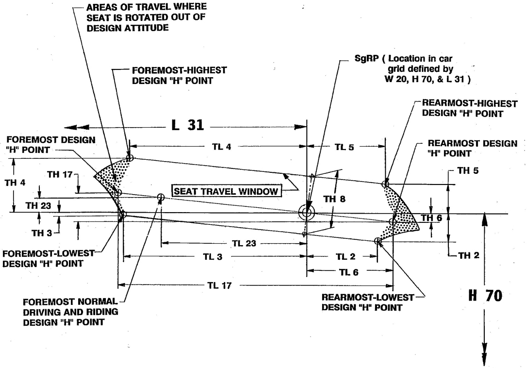
FIGURE 33—SEAT TRAVEL DIMENSIONS
5814.2.7 TL5-SGRP TO REARMOST-HIGHEST DESIGN H-POINT—The dimension measured horizontally from the SgRP to the rearmost location of full up Design H-Point. This measurement accounts for adjustments independent of track travel.
14.2.8 TH5-SGRP TO REARMOST-HIGHEST DESIGN H-POINT—The dimension measured vertically from the SgRP to the rearmost location of full up Design H-Point. This measurement includes vertical adjustment independent of track travel.
14.2.9 TL6-SGRP TO REARMOST DESIGN H-POINT—The dimension measured horizontally from the SgRP to the rearmost location of the Design H-Point. This measurement is based on Design H-Point travel path through the SgRP parallel to the fore/aft track travel path and does not account for independent vertical adjustment, if provided.
14.2.10 TH6-SGRP TO REARMOST DESIGN H-POINT—The dimension measured vertically from the SgRP to the rearmost location of the Design H-Point. This measurement is based on Design H-Point travel path through the SgRP parallel to the fore/aft track travel path and does not account for independent vertical adjustment, if provided.
14.2.11 TH8-VERTICAL DESIGN H-POINT ADJUSTMENT—The dimension measured normal from the lower Design.
H-Point travel path to upper Design H-Point travel path at the SgRP due to independent vertical adjustment modes.
14.2.12 TL17-DESIGN H-POINT TRAVEL—The dimension measured horizontally between the Design H-Point at the foremost and Rearmost Design H-Point positions.
14.2.13 TH17-DESIGN H-POINT RISE—The dimension measured vertically between the Design H-Point at the Foremost and Rearmost Design H-Point positions. Independent vertical adjustment, if provided, is not included.
14.2.14 TL23-NORMAL DRIVING AND RIDING SEAT-TRACK TRAVEL—The dimension measured horizontally between the SgRP and foremost normal driving and riding Design H-Point (not to include seat track travel used for purposes other than normal driving and riding positions).
14.2.15 TH23-NORMAL DRIVING AND RIDING DESIGN H-POINT RISE—The dimension measured between the SgRP and the foremost normal driving and riding Design H-Point (TL23) position.
5915. Numerical Index of Dimensions—Tables 3 to 9 list the W, L, and H dimensions in numerical order.
| Ident. | Definition | Revised | Section No. | Figure No. |
|---|---|---|---|---|
| W3 | Shoulder-room-front | 6.1.33 | 12 | |
| W4 | Shoulder-room-second | 6.2.30 | 12 | |
| W5 | Hip room-front | 6.1.34 | 12 | |
| W6 | Hip room-second | 6.2.31 | 12 | |
| W7 | Steering wheel center - Y coordinate | 6.6.24 | 12 | |
| W9 | Steering wheel maximum outside diameter | 6.6.25 | 12 | |
| W16 | Cushion width - front | 6.5.34 | 12 | |
| W20 | SgRP-front - Y coordinate | 6.1.35 | 12 | |
| W21 | Fiducial mark no. 1 - Y coordinate (See SAE J182A) | 5.1 | – | |
| W22 | Fiducial mark no. 2 - Y coordinate (See SAE J182A) | 5.2 | – | |
| W23 | Fiducial mark no. 3 - Y coordinate (See SAE J182A) | 5.3 | – | |
| W25 | SgRP - second - Y coordinate | 6.2.32 | 12 | |
| W26 | SgRP - third - Y coordinate | 6.4.21 | – | |
| W27 | Head clearance diagonal - driver | 6.1.36 | 12 | |
| W30 | Steering wheel to door clearance | 6.6.26 | – | |
| W31 | Elbow room - front | 6.1.37 | – | |
| W32 | Elbow room - second | 6.2.33 | – | |
| W33 | Head clearance diagonal - second | 6.2.34 | 12 | |
| W34 | Head clearance diagonal - third | 6.4.22 | 12 | |
| W35 | Head clearance lateral - driver | 6.1.38 | 12 | |
| W36 | Head clearance lateral - second | 6.2.35 | 12 | |
| W37 | Head clearance lateral - third | 6.4.23 | 12 | |
| W38 | Head clearance - minimum - driver | 6.1.39 | – | |
| W39 | Head clearance - minimum - second | 6.2.36 | – | |
| W40 | Head clearance - minimum - third | 6.4.24 | – | |
| W41 | Side glass radius | 6.6.27 | 17 | |
| W43 | Elbow room - third | 6.4.25 | – | |
| W85 | Shoulder room - third | 6.4.26 | 14 | |
| W86 | Hip room - third | 6.4.27 | 14 | |
| W101 | Tread - front | 7.1.1 | 17 | |
| W102 | Tread - rear | 7.1.2 | 17,18 | |
| W103 | Vehicle width | 7.1.3 | 17 | |
| W106 | Front fender width | 7.1.4 | 17 | |
| W107 | Rear fender width | 7.1.5 | 17 | |
| W116 | Body width - maximum | 7.1.6 | 17 | |
| W117 | Body width at SgRP - front | 7.1.7 | 17 | |
| W120 | Vehicle width - front doors open | 7.1.8 | 17,18 | |
| W121 | Vehicle width - rear doors open | 7.1.9 | 17,18 | |
| W122 | Tumble-home | 6.6.28 | 17 | |
| W201 | Cargo width - wheelhouse | 8.34 | 27,28 | |
| W203 | Rear opening width at floor | 8.35 | 27,28 | |
| W204 | Rear opening width at belt | 8.36 | 27,28 | |
| W205 | Rear opening width above belt | 8.37 | 27,28 | |
| W300 | Engine cover width - left | 6.1.40 | 11 | |
| W301 | Engine cover width - right | 6.1.41 | 11 | |
| W306 | Sleeper compartment width | 6.3.3 | 13 | |
| W409 | Vehicle width - tail doors open | 7.1.10 | 18 | |
| W410 | Vehicle Width - including outside mirrors | 7.1.11 | 18 | |
| W500 | Cargo width at floor | 8.38 | 18,28 |
| Ident. | Definition | Revised | Section No. | Figure No. |
|---|---|---|---|---|
| L3 | Compartment room - second | 6.2.19 | 8 | |
| L4 | Tire size - rear only if different than front | 7.4.20 | 22 | |
| L6 | Ball off foot to steering wheel center | × | 6.6.15 | — |
| L7 | Steering wheel torso clearance | 6.6.16 | 8 | |
| L9 | Cushion depth - front | 6.5.21 | 8 | |
| L10 | Effective cushion depth - front | 6.5.22 | 8 | |
| L11 | Accelerator heel point to steering wheel center | × | 6.6.17 | 10 |
| L12 | Effective cushion depth - second | 6.5.24 | 8 | |
| L13 | Brake pedal knee clearance | 6.6.18 | 8,30 | |
| L14 | Seatback thickness - front | 6.5.25 | 8 | |
| L15 | Seatback thickness - second | 6.5.26 | 8 | |
| L16 | Cushion depth - second | 6.5.27 | 8 | |
| L18 | Entrance foot clearance - front | 6.5.28 | 12 | |
| L19 | Entrance foot clearance - second | 6.5.29 | 12 | |
| L20 | Seatback thickness - third | 6.5.30 | — | |
| L21 | Cushion depth - third | 6.5.31 | — | |
| L22 | Steering wheel to seatback | 6.5.32 | — | |
| L24 | Effective cushion depth - third | 6.5.33 | — | |
| L27 | Cushion Angle - Front | 6.1.20 | — | |
| L30 | Front of dash - X coordinate | 7.3.1 | 8.22 | |
| L31 | SgRP - front - X coordinate | 6.1.21 | 8 | |
| L32 | SgRP - second to rear wheel centerline | 6.2.20 | 8 | |
| L33 | Maximum leg room - accelerator | × | 6.1.22 | — |
| L34 | Effective leg room - front | 6.1.23 | 9 | |
| L35 | SgRP - second - X coordinate | 6.2.21 | 8 | |
| L36 | SgRP - third - X coordinate | 6.4.12 | — | |
| L38 | Head clearance to windshield garnish - driver | 6.1.24 | 9 | |
| L39 | Head clearance to backlite gamish | 6.2.22 | 9 | |
| L40 | Torso (back) angle - front | 6.1.25 | 9 | |
| L41 | Torso (back) angle - second | 6.2.23 | 9 | |
| L42 | Hip angle - front | 6.1.26 | 9 | |
| L43 | Hip angle - second | 6.2.24 | 10 | |
| L44 | Knee angle - front | 6.1.27 | 10 | |
| L45 | Knee angle - second | 6.2.25 | 10 | |
| L46 | Foot angle - front | 6.1.28 | 10 | |
| L47 | Foot angle - second | 6.2.26 | 10 | |
| L48 | Knee clearance - second | 6.2.27 | 10 | |
| L50 | SgRP couple distance | 6.2.28 | 10 | |
| L51 | Effective leg room - second | 6.2.29 | 10 | |
| L52 | Brake pedal to accelerator | 6.6.19 | 10.30 | |
| L53 | SgRP - front to heel | 6.1.29 | 10 | |
| L54 | Fiducial mark no. 1 - X coordinate | 5.1 | — 61 | |
| L55 | Fiducial mark no. 2 - X coordinate | 5.2 | — | |
| L56 | Fiducial mark no. 3 - X coordinate | 5.3 | — | |
| L62 | Knee clearance - front | 6.1.30 | — | |
| L85 | SgRP couple distance - third | 6.4.13 | 14 | |
| L86 | Effective leg room - third | 6.4.14 | 14 | |
| L87 | Knee clearance - third | 6.4.15 | 14 | |
| L88 | Torso (back) angle - third | 6.4.16 | 14 | |
| L89 | Hip angle - third | 6.4.17 | 14 | |
| L90 | Knee angle - third | 6.4.18 | 14 | |
| L91 | Foot angle - third | 6.4.19 | 14 | |
| L92 | Compartment room - third | 6.4.20 | — | |
| L101 | Wheelbase | 7.3.2 | 3,22 | |
| L103 | Vehicle length | 7.3.3 | 3,22 | |
| L104 | Overhang - front | 7.3.4 | 3,22 | |
| L105 | Overhang - rear | 7.3.5 | 3,22 | |
| L106 | Overhang - front - RPO | 7.3.6 | 3,22 | |
| L107 | Overhang - rear - RPO | 7.3.7 | 3,22 | |
| L108 | Vehicle length - RPO | 7.3.8 | 3,22 | |
| L114 | Front wheel centerline to front SgRP | 6.1.30 | 8 | |
| L123 | Upper structure length | 7.3.9 | 3 | |
| L125 | Cowl point - X coordinate | 7.3.10 | 3 | |
| L126 | Front end length | 7.3.11 | 3 | |
| L127 | Rear wheel centerline - X coordinate | 7.3.12 | 3,22 | |
| L128 | Front wheel centerline - X coordinate | 7.3.13 | 3,22 | |
| L129 | Rear end length | 7.3.14 | 3 | |
| L200 | Cargo length - open - front | 8.15 | 27 | |
| L201 | Cargo length - open - second | 8.16 | 24 | |
| L202 | Cargo length - closed - front | 8.17 | 24,26 | |
| L203 | Cargo length - closed - second | 8.18 | 24,26 | |
| L204 | Cargo length at belt - front | 8.19 | 24,26 | |
| L205 | Cargo length at belt - second | 8.20 | 24,26 | |
| L208 | Cargo length at front seatback height - hatchback | 8.21 | 24,26 | |
| L209 | Cargo length at floor - front - hatchback | 8.22 | 24 | |
| L210 | Cargo length at second seatback height - hatch back | × | 8.23 | 24 |
| L211 | Cargo length at floor - second - hatchback | 8.24 | 24 | |
| L308 | Engine cover length | 6.1.32 | 11 | |
| L324 | SgRP to windshield upper DLO | 6.6.20 | 11 | |
| L330 | Clutch pedal to steering wheel clearance | 6.6.21 | 13 | |
| L332 | Accelerator pedal to steering wheel clearance | 6.6.22 | 13 | |
| L350 | Sleeper compartment length | 6.3.2 | 13 | |
| L403 | Front of bumper to back of cab | 7.3.15 | 22 | |
| L404 | Cab to rear axle | 7.3.16 | 22 | |
| L408 | Front bumper to cab - tilt cab servicing position | 7.3.17 | 21 | |
| L409 | Cab servicing tilt angle | 7.3.18 | 21 62 | |
| L410 | Cab length | 7.3.19 | 22 | |
| L411 | Dual rear axle spacing | 7.3.20 | 22 | |
| L421 | Max dist. from accel. heel pt to intersection of frt and top surface of hood | 6.6.23 | 13 | |
| L504 | Cab to pickup body | 8.25 | 26 | |
| L505 | Pickup body length at floor | 8.26 | 26 | |
| L506 | Pickup body length at top of body | 8.27 | 26 | |
| L507 | Cargo body overall length | 8.28 | 26 | |
| L508 | Side cargo door opening length | 8.29 | 26 | |
| L509 | Cargo length - closed - third | 8.30 | 26 | |
| L510 | Cargo length at belt - third | 8.31 | 26 | |
| L511 | Front cargo surface | 8.32 | 26 | |
| L512 | Cargo length to engine cover | 8.33 | 26 |
| Ident. | Dimension | Revised | Section No. | Figure No. |
|---|---|---|---|---|
| H5 | SgRP - front to ground | 6.1.2 | 4 | |
| H6 | SgRP - front to windshield lower DLO | 6.6.1 | 5 | |
| H10 | SgRP - second to ground | 6.2.2 | 4 | |
| H11 | Entrance height - front | 6.5.1 | 5 | |
| H12 | Entrance height - second | 6.5.2 | 5 | |
| H13 | Steering wheel to centerline of thigh | 6.6.2 | 5 | |
| H14 | Eyellipse to bottom of inside rearview mirror | 6.6.3 | 5 | |
| H17 | Accelerator heel point to steering wheel center | 6.6.4 | 5 | |
| H18 | Steering wheel angle | 6.6.5 | 5 | |
| H25 | Belt height - front | 6.6.6 | 15 | |
| H26 | Interior body height - front at zero Y plane | 6.1.3 | 5 | |
| H27 | Interior body height - front at SgRP Y plane | 6.1.4 | 5 | |
| H28 | Interior body height - second at zero Y plane | 6.2.3 | 4 | |
| H29 | Interior body height - second at SgRP Y plane | 6.2.4 | 4 | |
| H30 | SgRP - front to heel | 6.1.5 | 4 | |
| H31 | SgRP - second to heel | 6.2.5 | 4 | |
| H32 | Cushion deflection - front | 6.5.3 | 4 | |
| H33 | Cushion deflection - second | 6.5.4 | 4 | |
| H34 | Cushion deflection - third | 6.5.5 | 14 | |
| H35 | Vertical head clearance - driver | 6.1.6 | 12 | |
| H36 | Head clearance vertical - second | 6.2.6 | 12 | |
| H37 | Headlining to roof panel - front | 6.1.7 | 4 | |
| H38 | Headlining to roof panel - second | 6.2.7 | 4 | |
| H39 | Head clearance vertical - third | 6.4.3 | 12 | |
| H40 | Steering wheel to accelerator heel point | 6.5.6 | 5 | |
| H41 | Minimum head clearance - driver | 6.1.8 | 12 | |
| H42 | Minimum head clearance - second | 6.2.8 | 12 | |
| H49 | Eyellipse to top of steering wheel | 6.6.7 | 6 | |
| H50 | Upper-body opening to ground - front | 6.5.7 | 6 | |
| H51 | Upper-body opening to ground - second | 6.5.8 | 6 | |
| H53 | D-point - front to heel | 6.1.9 | 6 | |
| H54 | D-point - center passenger - front to tunnel | 6.1.10 | 6 | |
| H55 | D-point - center passenger - second to tunnel | 6.2.9 | 6 | |
| H56 | D-point - front to floor | 6.1.11 | 6 | |
| H57 | D-point - second to floor | 6.2.10 | 6 | |
| H60 | D-point to heel point - second | 6.2.11 | 6 | |
| H61 | Effective heel room - front | 6.1.12 | 6 | |
| H62 | D-point to heel point - third | 6.4.4 | — | |
| H63 | Effective head room - second | 6.2.12 | 6 | |
| H64 | SgRP - front to windshield upper DLO | 6.6.8 | 5 | |
| H65 | D-point - front differential, side to center | 6.1.13 | 6 | |
| H66 | D-point - differential, side to center - second | 6.2.13 | 6 64 | |
| H67 | Floor covering thickness - undepressed - front | 6.1.14 | 7 | |
| H68 | Floor covering thickness - depressed - front | 6.1.15 | 7 | |
| H69 | Exit height - second | 6.5.9 | 7 | |
| H70 | SgRP - front - Z coordinate | 6.1.16 | 7 | |
| H71 | SgRP - second - Z coordinate | 6.2.14 | 7 | |
| H72 | Floor covering thickness - undepressed - second | 6.2.15 | 7 | |
| H73 | Floor covering thickness - depressed - second | 6.2.16 | 7 | |
| H74 | Steering wheel to cushion | 6.5.10 | 7 | |
| H75 | Effective T-point head room - front | 6.1.17 | 7 | |
| H76 | Effective T-point head room - second | 6.2.17 | 7 | |
| H77 | Seatback height - front | 6.5.11 | 7 | |
| H78 | Seatback height - second | 6.5.12 | 7 | |
| H79 | SgRP differential - side to center - front | 6.1.18 | — | |
| H80 | SgRP - differential, side to center - second | 6.2.18 | — | |
| H81 | Fiducial mark no. 1 - Z coordinate (see SAE J182A) | 5.1 | — | |
| H82 | Fiducial mark no. 2 - Z coordinate (see SAE J182A) | 5.2 | — | |
| H83 | Fiducial mark no. 3 - Z coordinate (see SAE J182A) | 5.3 | — | |
| H84 | Headlining to roof - third | 6.4.5 | — | |
| H85 | SgRP third to ground | 6.4.6 | 14 | |
| H86 | Effective head room - third | 6.4.7 | 14 | |
| H87 | SgRP - third to heel - vertical | 6.4.8 | 14 | |
| H88 | SgRP - third - Z coordinate | 6.4.9 | 14 | |
| H89 | Effective T-point head room - third | 6.4.10 | 14 | |
| H90 | D-point - third to floor | 6.4.11 | — | |
| H92 | Seatback height - third | 6.5.13 | — | |
| H94 | Steering wheel to cushion - minimum | 6.5.14 | — | |
| H101 | Vehicle height | 7.2.1 | 15.20 | |
| H102 | Front bumper to ground | 7.4.1 | 15 | |
| H103 | Front bumper to ground - curb weight | 7.4.2 | 15 | |
| H104 | Rear bumper to ground | 7.4.3 | 15 | |
| H105 | Rear bumper to ground - curb weight | 7.4.4 | 15 | |
| H106 | Angle of approach | 7.4.5 | 23 | |
| H107 | Angle of departure | 7.4.6 | 23 | |
| H108 | Static load - tire radius - front | 7.4.7 | 23 | |
| H109 | Static load - tire radius - rear | 7.4.8 | 23 | |
| H111 | Rocker panel - rear to ground | 7.2.2 | 15,20 | |
| H112 | Rocker panel - front to ground | 7.2.3 | 15,20 | |
| H114 | Cowl point to ground | 7.2.4 | 15 | |
| H115 | Step height - front | 6.5.15 | 15,20 | |
| H116 | Step height - second | 6.5.16 | 15,24 | |
| H121 | Backlight slope angle | 6.6.9 | 15,20 | |
| H122 | Windshield slope angle | 6.6.10 | 15,20 | |
| H123 | Eyellipse to backlight upper opening | 6.6.11 | 6 | |
| H124 | Vision angle to windshield upper DLO | 6.6.12 | 6 65 | |
| H125 | Headlamp to ground | 7.2.5 | 16 | |
| H126 | Taillamp to ground | 7.2.6 | 16 | |
| H127 | Headlamp to ground - curb weight | 7.2.7 | 16 | |
| H128 | Taillamp to ground - curb weight | 7.2.8 | 16 | |
| H129 | Windshield Slope - Driver Vision | 6.6.13 | — | |
| H130 | Step height - front (curb weight) | 6.5.17 | 16,20 | |
| H131 | Step height - second (curb weight) | 6.5.18 | 16 | |
| H132 | Bottom of door open - front to ground | 7.2.9 | 16,20 | |
| H133 | Bottom of door closed - front to ground | 7.2.10 | 16,20 | |
| H134 | Bottom of door open - rear to ground | 7.2.11 | 16 | |
| H135 | Bottom of door closed - rear to ground | 7.2.12 | 16 | |
| H136 | Zero Z plane to ground - front | 7.2.13 | 16,20 | |
| H137 | Zero Z plane to ground - rear | 7.2.14 | 16,20 | |
| H138 | Deck point to ground | 7.2.15 | 16 | |
| H139 | Bottom of door ajar - front to ground | 7.2.16 | 19 | |
| H140 | Bottom of door ajar - rear to ground | 7.2.17 | 19 | |
| H147 | Ramp breakover angle | 7.4.9 | 23 | |
| H148 | Front suspension to ground | 7.4.10 | 23 | |
| H149 | Oil pan to ground | 7.4.11 | 23 | |
| H150 | Flywheel/converter housing and transmission assembly to ground | 7.4.12 | 23 | |
| H151 | Frame structure to ground | 7.4.13 | 23 | |
| H152 | Exhaust system to ground | 7.4.14 | 23 | |
| H153 | Rear axie differential to ground | 7.4.15 | 23 | |
| H154 | Fuel tank to ground | 7.4.16 | 23 | |
| H155 | Spare tire well to ground | 7.4.17 | 23 | |
| H156 | Minimum running ground clearance | 7.4.18 | — | |
| H158 | Roof thickness | 7.2.18 | 19 | |
| H159 | Side glass height | 7.2.19 | 19 | |
| H160 | Body thickness | 7.2.20 | 19 | |
| H161 | Fiducial mark no. 1 - Z coordinate to ground at curb weight | 5.1 | — | |
| H162 | Fiducial mark no. 2 - Z coordinate to ground at curb weight | 5.2 | — | |
| H163 | Fiducial mark no. 1 - Z coordinate to ground | 5.1 | — | |
| H164 | Fiducial mark no. 2 - Z coordinate to ground | 5.2 | — | |
| H167 | Fiducial mark no. 3 - Z coordinate to ground at curb weight | 5.3 | — | |
| H168 | Fiducial mark no. 3 - Z coordinate to ground | 5.3 | — | |
| H195 | Liftover height | 7.2.21 | 19 | |
| H196 | Liftover height - curb weight | 7.2.22 | 19 | |
| H197 | Seatback to load floor height - front | 8.1 | 24 | |
| H198 | Seatback to load floor height - second | 8.2 | 24 | |
| H199 | Seatback to load floor height - third | 8.3 | — | |
| H201 | Cargo height | 8.4 | 27 | |
| H202 | Rear opening height | 8.5 | 27 | |
| H250 | Tailgate to ground (curb weight) | 8.6 | 27 | |
| H311 | Engine cover height | 6.1.19 | 11 66 | |
| H326 | Seat Cushion height - front | 6.5.19 | 11 | |
| H350 | Sleeper compartment height | 6.3.1 | 13 | |
| H404 | Maximum overall height - tilt cab servicing | 7.2.23 | 21 | |
| H420 | Distance from accel. heel pt to intersection of frt and top surface of hood | 6.6.14 | 13 | |
| H430 | Body height | 7.2.24 | 20 | |
| H431 | Vehicle height - curb weight | 7.2.25 | 20 | |
| H436 | Zero Z plane to ground - front (curb weight) | 7.2.26 | 20 | |
| H437 | Zero Z plane to ground - rear (curb weight) | 7.2.27 | 20 | |
| H445 | Second step height - front | 6.5.20 | 25 | |
| H446 | Second step height - second | 6.5.21 | 25 | |
| H501 | Cargo floor height to ground | 8.7 | 25 | |
| H502 | Cargo floor height to ground (curb weight) | 8.8 | 25 | |
| H503 | Pickup body height | 8.9 | 25 | |
| H504 | Wheelhouse height | 8.10 | 25 | |
| H505 | Maximum cargo height | 8.11 | 25 | |
| H506 | Cargo floor height | 8.12 | 25 | |
| H507 | Frame height | 8.13 | 25 | |
| H508 | Side cargo door opening height | 8.14 | 25 |
| Ident. | Dimension | Revised | Section No. | Figure No. |
|---|---|---|---|---|
| V1 | Luggage Capacity | 9.0 | — | |
| V2 | Station wagon cargo volume maximum | 10.1 | — | |
| V3 | Hatchback cargo volume maximum | 10.2 | — | |
| V4 | Hidden luggage capacity - rear of front seat | 10.3 | — | |
| V5 | Open trucks and MPV cargo volume | × | 10.4 | — |
| V6 | Enclosed truck and MPV cargo volume - maximum | × | 10.5 | — |
| V7 | Enclosed truck and MPV cargo volume - behind second seat | × | 10.6 | — |
| V9 | Enclosed truck and MPV cargo volume - behind third seat | × | 10.7 | — |
| V10 | Station wagon cargo volume maximum - behind second seat | 10.8 | — | |
| V11 | Hatchback cargo volume - behind second seat | 10.9 | — | |
| V210 | Enclosed luggage compartment volume | 11.2.1 | — | |
| V211 | Open luggage compartment volume - behind second seat | 11.2.2 | — | |
| V212 | Open luggage compartment - behind first seat | 11.2.3 | — | |
| V213 | Open luggage compartment - behind third seat | 11.2.4 | — | |
| V214 | Largest luggage volume | 11.2.5 | — |
| Ident. | Dimension | Revised | Section No. | Figure No. |
|---|---|---|---|---|
| S1 | Windshield area | 12.0 | — | |
| S2 | Side window area | 12.0 | — | |
| S3 | Backlight areas | 12.0 | — | |
| S4 | Total areas | 12.0 | — |
| Ident. | Dimension | Revised | Section No. | Figure No. |
|---|---|---|---|---|
| PH1 | Clutch pedal pad height | 13.2.16 | 32 | |
| PH2 | Brake pedal pad height | 13.2.17 | 32 | |
| PH3 | Accelerator pedal height | 13.2.18 | 32 | |
| PH30 | Bottom of accelerator pedal to floor | 13.2.19 | 30,31,32 | |
| PH31 | Centerline of brake pedal to floor | 13.2.20 | 30,31 | |
| PH32 | Centerline of clutch pedal to floor | 13.2.21 | 31 | |
| PL1 | Accelerator to brake liftoff | 13.2.3 | 30,31 | |
| PL2 | Brake to clutch liftoff | 13.2.4 | 31 | |
| PW1 | Clutch pedal width | 13.2.5 | 32 | |
| PW2 | Brake pedal width | 13.2.6 | 32 | |
| PW3 | Accelerator pedal pad width | 13.2.7 | 32 | |
| PW4 | ‘Y’ coordinate at centerline of accelerator pedal pad | 13.2.8 | 30,31,32 | |
| PW10 | Right edge of brake pedal to centerline of driver | 13.2.9 | 30,31 | |
| PW11 | Accelerator to brake lateral separation | 13.2.10 | 30,31 | |
| PW20 | Clutch pedal foot clearance | 13.2.11 | 31 | |
| PW21 | Left foot space | 13.2.12 | 30 | |
| PW22 | Lateral space for accelerator pedal operation | 13.2.13 | 30,31 | |
| PW30 | Brake to clutch lateral separation | 13.2.14 | 31 | |
| PW31 | Accelerator pedal to right foot support structure | 13.2.15 | 30,31 |
| Ident. | Dimension | Revised | Section No. | Figure No. |
|---|---|---|---|---|
| TH2 | SgRP to rearmost - lowest design H-point | 14.2.2 | 33 | |
| TH3 | SgRP to foremost - lowest design H-point | 14.2.4 | 33 | |
| TH4 | SgRP to foremost - highest design H-point | 14.2.6 | 33 | |
| TH5 | SgRP to rearmost - highest design H-point | 14.2.8 | 33 | |
| TH6 | SgRP to rearmost design H-point | 14.2.10 | 33 | |
| TH8 | Vertical design H-point adjustment | 14.2.11 | 33 | |
| TH17 | Design H-point rise | 14.2.13 | 33 | |
| TH23 | Normal driving and riding design H-point rise | 14.2.15 | 33 | |
| TL2 | SgRP to rearmost - lowest design H-point | 14.2.1 | 33 | |
| TL3 | SgRP to foremost - lowest design H-point | 14.2.3 | 33 | |
| TL4 | SgRP to foremost - highest design H-point | 14.2.5 | 33 | |
| TL5 | SgRP to rearmost - highest design H-point | 14.2.7 | 33 | |
| TL6 | SgRP to rearmost design H-point | 14.2.9 | 33 | |
| TL17 | Design H-point travel | 14.2.12 | 33 | |
| TL23 | Normal driving and riding seat - track travel | 14.2.14 | 33 |
16. Alphabetical Index of Dimensions—Table 10 lists the W, L, and H dimensions in alphabetical order. Some listings have alternate titles and appear in two alphabetical locations.
| Ident. | Definition | Revised | Section No. | Figure No. |
|---|---|---|---|---|
| L11 | Accelerator heel point to steering wheel center | × | 6.6.17 | 10 |
| H17 | Accelerator heel point to steering wheel center | 6.6.4 | 5 | |
| PH3 | Accelerator pedal pad height | 13.2.18 | 32 | |
| PW3 | Accelerator pedal pad width | 13.2.7 | 32 | |
| PW31 | Accelerator pedal to right foot support structure | 13.2.15 | 30,31 | |
| L332 | Accelerator pedal to steering wheel clearance | 6.6.22 | 13 | |
| PW11 | Accelerator to brake lateral separation | 13.2.10 | 30,31 | |
| PL1 | Accelerator to brake liftoff | 13.2.3 | 30,31 | |
| H106 | Angle of approach | 7.4.5 | 23 | |
| H107 | Angle of departure | 7.4.6 | 23 | |
| S3 | Backlight areas | 12.0 | — | |
| H121 | Backlight slope angle | 6.6.9 | 15,20 | |
| L6 | Ball off foot to steering wheel center | × | 6.6.15 | |
| H25 | Belt height - front | 6.6.66 | 15 | |
| H430 | Body height | 7.2.24 | 20 | |
| H160 | Body thickness | 7.2.20 | 19 | |
| W410 | Body Width - including outside mirrors | 7.1.11 | 18 | |
| W116 | Body width - maximum | 7.1.6 | 17 | |
| W117 | Body width - SgRP | 7.1.7 | 17 | |
| PH30 | Bottom of accelerator pedal to floor | 13.2.19 | 30,31,32 | |
| H139 | Bottom of door ajar - front to ground | 7.2.16 | 19 | |
| H140 | Bottom of door ajar - rear to ground | 7.2.17 | 19 | |
| H133 | Bottom of door closed - front to ground | 7.2.10 | 16,20 | |
| H135 | Bottom of door closed - rear to ground | 7.2.12 | 16 | |
| H132 | Bottom of door open - front to ground | 7.2.9 | 16,20 | |
| H134 | Bottom of door open - rear to ground | 7.2.11 | 16 | |
| L13 | Brake pedal knee clearance | 6.6.18 | 8,30 | |
| PH2 | Brake pedal pad height | 13.2.17 | 32 | |
| L52 | Brake pedal to accelerator | 6.6.19 | 10,30 | |
| PW2 | Brake pedal width | 13.2.6 | 32 | |
| PW30 | Brake to clutch lateral separation | 13.2.14 | 31 | |
| PL2 | Brake to clutch liftoff | 13.2.4 | 31 | |
| H103 | Bumper to ground at curb weight - front | 7.4.2 | 15 | |
| H105 | Bumper to ground at curb weight - rear | 7.4.4 | 15 | |
| H102 | Bumper to ground - front | 7.4.1 | 15 | |
| H104 | Bumper to ground - Rear | 7.4.3 | 15 | |
| L410 | Cab length | 7.3.19 | 22 | |
| L409 | Cab servicing tilt angle | 7.3.18 | 21 | |
| L504 | Cab to pickup body | 8.25 | 26 | |
| L404 | Cab to rear axle | 7.3.16 | 22 69 | |
| L507 | Cargo body overall length | 8.28 | 26 | |
| L508 | Cargo door opening length - side | 8.29 | 26 | |
| H506 | Cargo floor height | 8.12 | 25 | |
| H501 | Cargo floor height to ground | 8.7 | 25 | |
| H502 | Cargo floor height to ground (curb weight) | 8.8 | 25 | |
| H201 | Cargo height | 8.4 | 27 | |
| L204 | Cargo length at belt - front | 8.19 | 24,26 | |
| L205 | Cargo length at belt - second | 8.20 | 24,26 | |
| L510 | Cargo length at belt - third | 8.31 | 26 | |
| L209 | Cargo length at floor - front - hatchback | 8.22 | 24 | |
| L211 | Cargo length at floor - second - hatchback | 8.24 | 24 | |
| L208 | Cargo length at front seatback height - hatchback | 8.21 | 24,26 | |
| L210 | Cargo length at second seatback height - hatchback | × | 8.23 | 24 |
| L512 | Cargo length to engine cover | 8.33 | 26 | |
| L202 | Cargo length - closed - front | 8.17 | 24,26 | |
| L203 | Cargo length - closed - second | 8.18 | 24,26 | |
| L509 | Cargo length - closed - third | 8.30 | 26 | |
| L200 | Cargo length - open - front | 8.15 | 27 | |
| L201 | Cargo length - open - second | 8.16 | 24 | |
| L511 | Cargo surface - front | 8.32 | 26 | |
| W500 | Cargo width at floor | 8.38 | 18,28 | |
| W201 | Cargo width - wheelhouse | 8.34 | 27,28 | |
| PH31 | Centerline of brake pedal to floor | 13.2.20 | 30,31 | |
| PH32 | Centerline of clutch pedal to floor | 13.2.21 | 31 | |
| PW20 | Clutch pedal foot clearance | 13.2.11 | 31 | |
| PH1 | Clutch pedal pad height | 13.2.16 | 32 | |
| L330 | Clutch pedal to steering wheel clearance | 6.6.21 | 13 | |
| PW1 | Clutch pedal width | 13.2.5 | 32 | |
| L3 | Compartment room -second | 6.2.19 | 8 | |
| L92 | Compartment room - third | 6.4.20 | — | |
| L50 | Couple - SgRP distance | 6.2.28 | 10 | |
| L85 | Couple - SgRP distance - third | 6.4.13 | 14 | |
| H114 | Cowl point to ground | 7.2.4 | 15 | |
| L125 | Cowl point - X coordinate | 7.3.10 | 3 | |
| L27 | Cushion angle - front | 6.1.20 | — | |
| H32 | Cushion deflection - front | 6.5.3 | 4 | |
| H33 | Cushion deflection - second | 6.5.4 | 4 | |
| H34 | Cushion deflection - third | 6.5.5 | 14 | |
| L10 | Cushion depth - effective front | 6.5.23 | 8 | |
| L12 | Cushion depth - effective - second | 6.5.24 | 8 | |
| L24 | Cushion Depth - effective - third | 6.5.33 | — | |
| L9 | Cushion depth - front | 6.5.22 | 8 | |
| L16 | Cushion depth - second | 6.5.27 | 8 | |
| L21 | Cushion depth - third | 6.5.31 | — 70 | |
| W16 | Cushion width-front | 6.5.34 | 12 | |
| L30 | Dash-front of-X coordinate | 7.3.1 | 8,22 | |
| H138 | Deck point to ground | 7.2.15 | 16 | |
| TH17 | Design H-point rise | 14.2.13 | 33 | |
| TL17 | Design H-point travel | 14.2.12 | 33 | |
| L38 | Head clearance to windshield garnish - driver | 6.1.24 | 9 | |
| W38 | Head clearance - minimum - driver | 6.1.38 | — | |
| H35 | Driver head clearance - vertical | 6.1.6 | 12 | |
| L411 | Dual rear axle spacing | 7.3.20 | 22 | |
| H60 | D-point to heel point - second | 6.2.11 | 6 | |
| H62 | D-point to heel point - third | 6.4.4 | — | |
| H54 | D-point - center passenger - front to tunnel | 6.1.10 | 6 | |
| H55 | D-point - center passenger - second to tunnel | 6.2.9 | 6 | |
| H65 | D-point - front- differential, side to center | 6.1.13 | 6 | |
| H66 | D-point - differential, side to center - second | 6.2.13 | 6 | |
| H56 | D-point - front to floor | 6.1.11 | 6 | |
| H53 | D-point - front to heel | 6.1.9 | 6 | |
| H57 | D-point - second to floor | 6.2.10 | 6 | |
| H90 | D-point - third to floor | 6.4.11 | — | |
| L10 | Effective cushion depth - front | 6.5.23 | 8 | |
| L12 | Effective cushion depth - second | 6.5.24 | 8 | |
| L24 | Effective cushion depth - third | 6.5.33 | — | |
| H61 | Effective head room - front | 6.1.12 | 6 | |
| H63 | Effective head room - second | 6.2.12 | 6 | |
| H86 | Effective head room - third | 6.4.7 | 14 | |
| L34 | Effective leg room - front | 6.1.23 | 9 | |
| L51 | Effective leg room - second | 6.2.29 | 10 | |
| L86 | Effective leg room - third | 6.4.14 | 14 | |
| H89 | Effective T-point head room - third | 6.4.10 | 14 | |
| H75 | Effective T-point head room - front | 6.1.17 | 7 | |
| H76 | Effective T-point head room - second | 6.2.17 | 7 | |
| W31 | Elbow room - front | 6.1.37 | — | |
| W32 | Elbow room - second | 6.2.33 | — | |
| W43 | Elbow room - third | 6.4.25 | — | |
| V210 | Enclosed luggage compartment volume | 11.2.1 | — | |
| V7 | Enclosed truck and MPV cargo volume - behind second seat | × | 10.6 | — |
| V9 | Enclosed truck and MPV cargo volume - behind third seat | × | 10.7 | — |
| V6 | Enclosed truck and MPV cargo volume - maximum | × | 10.5 | — |
| H311 | Engine cover height | 6.1.19 | 11 | |
| L308 | Engine cover length | 6.1.33 | 11 | |
| W300 | Engine cover width - left | 6.1.40 | 11 | |
| W301 | Engine cover width - right | 6.1.41 | 11 | |
| L18 | Entrance foot clearance - front | 6.5.28 | 12 | |
| L19 | Entrance foot clearance - second | 6.5.29 | 12 71 | |
| H11 | Entrance height - front | 6.5.1 | 5 | |
| H12 | Entrance height - second | 6.5.2 | 5 | |
| H152 | Exhaust system to ground | 7.4.14 | 23 | |
| H69 | Exit height - second | 6.5.9 | 7 | |
| H123 | Eyellipse to backlight upper opening | 6.6.11 | 6 | |
| H14 | Eyellipse to bottom of inside rearview mirror | 6.6.3 | 5 | |
| H49 | Eyellipse to top of steering wheel | 6.6.7 | 6 | |
| W106 | Fender width - front | 7.1.4 | 17 | |
| W107 | Fender width - rear | 7.1.5 | 17 | |
| H167 | Fiducial mark no. 3 - Z coordinate to ground at curb weight | 5.3 | — | |
| L54 | Fiducial mark no. 1 - X coordinate | 5.1 | — | |
| W21 | Fiducial mark no. 1 - Y coordinate (See SAE J182A) | 5.1 | — | |
| H163 | Fiducial mark no. 1 - Z coordinate to ground | 5.1 | — | |
| H161 | Fiducial mark no. 1 - Z coordinate to ground at curb weight | 5.1 | — | |
| H81 | Fiducial mark no. 1 - Z coordinate (See SAE J182A) | 5.1 | — | |
| L55 | Fiducial mark no. 2 - X coordinate | 5.2 | — | |
| W22 | Fiducial mark no. 2 - Y coordinate (See SAE J182A) | 5.2 | — | |
| H164 | Fiducial mark no. 2 - Z coordinate to ground | 5.2 | — | |
| H162 | Fiducial mark no. 2 - Z coordinate to ground at curb weight | 5.2 | — | |
| H82 | Fiducial mark no. 2 - Z coordinate (See SAE J182A) | 5.2 | — | |
| L56 | Fiducial mark no. 3 - X coordinate | 5.3 | — | |
| W23 | Fiducial mark no. 3 - Y coordinate (See SAE J182A) | 5.3 | — | |
| H168 | Fiducial mark no. 3 - Z coordinate to ground | 5.3 | — | |
| H83 | Fiducial mark no. 3 - Z coordinate (See SAE J182A) | 5.3 | — | |
| H68 | Floor covering thickness - depressed - front | 6.1.15 | 7 | |
| H73 | Floor covering thickness - depressed - second | 6.2.16 | 7 | |
| H67 | Floor covering thickness - undepressed - front | 6.1.14 | 7 | |
| H72 | Floor covering thickness - undepressed - second | 6.2.15 | 7 | |
| H150 | Flywheel/converter housing and transmission assembly to ground | 7.4.12 | 23 | |
| L46 | Foot angle - front | 6.1.28 | 10 | |
| L47 | Foot angle - second | 6.2.26 | 10 | |
| L91 | Foot angle - third | 6.4.19 | 14 | |
| L18 | Foot clearance - entrance - front | 6.5.28 | 12 | |
| L19 | Foot clearance - entrance - second | 6.5.29 | 12 | |
| H507 | Frame height | 8.13 | 25 | |
| H151 | Frame structure to ground | 7.4.13 | 23 | |
| L408 | Front bumper to cab - tilt cab servicing position | 7.3.17 | 21 | |
| H102 | Front bumper to ground | 7.4.1 | 15 | |
| H103 | Front bumper to ground - curb weight | 7.4.2 | 15 | |
| L511 | Front cargo surface | 8.32 | 26 | |
| L126 | Front end length | 7.3.11 | 3 | |
| W106 | Front fender width | 7.1.4 | 17 | |
| L403 | Front of bumper to back of cab | 7.3.15 | 22 | |
| L30 | Front of dash - X coordinate | 7.3.1 | 8.22 72 | |
| H197 | Front seatback to load floor height | 8.1 | 24 | |
| H148 | Front suspension to ground | 7.4.10 | 23 | |
| L114 | Front wheel centerline to front SgRP | 6.1.31 | 8 | |
| L128 | Front wheel centerline - X coordinate | 7.3.13 | 3.22 | |
| H154 | Fuel tank to ground | 7.4.13 | 23 | |
| V3 | Hatchback cargo volume maximum | 10.2 | — | |
| V11 | Hatchback cargo volume - behind second seat | 10.9 | — | |
| W27 | Head clearance diagonal - driver | 6.1.36 | 12 | |
| W33 | Head clearance diagonal - second | 6.2.34 | 12 | |
| W34 | Head clearance diagonal - third | 6.4.22 | 12 | |
| W35 | Head clearance lateral - driver | 6.1.38 | 12 | |
| W36 | Head clearance lateral - second | 6.2.35 | 12 | |
| W37 | Head clearance lateral - third | 6.4.23 | 12 | |
| L39 | Head clearance to backlite garnish | 6.2.22 | 9 | |
| L38 | Head clearance to windshield garnish - driver | 6.1.24 | 9 | |
| W38 | Head clearance - Driver minimum | 6.1.39 | — | |
| W39 | Head clearance - minimum - second | 6.2.36 | — | |
| W40 | Head clearance - minimum - third | 6.4.24 | — | |
| H36 | Head clearance vertical - second | 6.2.6 | 12 | |
| H39 | Head clearance vertical - third | 6.4.3 | 12 | |
| H63 | Head room, effective - second | 6.2.12 | 6 | |
| H86 | Head room, effective - third | 6.4.7 | 14 | |
| H89 | Head room, T-point effective - third | 6.4.10 | 14 | |
| H75 | Head room, T-point, effective - front | 6.1.17 | 7 | |
| H61 | Head room - effective - front | 6.1.12 | 6 | |
| H125 | Headlamp to ground | 7.2.5 | 16 | |
| H127 | Headlamp to ground - curb weight | 7.2.7 | 16 | |
| H37 | Headlining to roof panel - front | 6.1.7 | 4 | |
| H38 | Headlining to roof panel - second | 6.2.7 | 4 | |
| H84 | Headlining to roof - third | 6.4.5 | — | |
| H76 | Head room, T-point, effective - second | 6.2.17 | 7 | |
| H17 | Heel point - accelerator to steering wheel center | 6.6.4 | 5 | |
| L11 | Heel point - Accelerator - to steering wheel center | 6.6.17 | 10 | |
| H101 | Height - Vehicle overall | 7.2.1 | 15,20 | |
| V4 | Hidden luggage capacity - rear of front seat | 10.3 | — | |
| L42 | Hip angle - front | 6.1.25 | 9 | |
| L43 | Hip angle - second | 6.2.24 | 10 | |
| L89 | Hip angle - third | 6.4.17 | 14 | |
| W5 | Hip room - front. | 6.1.34 | 12 | |
| W6 | Hip room - second | 6.2.31 | 12 | |
| W86 | Hip room - third | 6.4.27 | 14 | |
| H29 | Interior body height - second at SgRP Y plane | 6.2.4 | 4 | |
| H28 | Interior body height - second at zero Y plane | 6.2.3 | 4 | |
| H27 | Interior body height - front at SgRP Y plane | 6.1.4 | 5 73 | |
| H26 | Interior body height - front at zero Y plane | 6.1.3 | 6 | |
| L44 | Knee angle - front | 6.1.27 | 10 | |
| L45 | Knee angle - second | 6.2.25 | 10 | |
| L62 | Knee clearance - front | 6.1.30 | — | |
| L48 | Knee clearance - second | 6.2.27 | 10 | |
| L87 | Knee clearance - third | 6.4.15 | 14 | |
| L90 | Knee room - third | 6.4.18 | 14 | |
| V214 | Largest luggage volume | 11.2.5 | — | |
| PW22 | Lateral space for accelerator pedal operation | 13.2.13 | 30,31 | |
| PW21 | Left foot space | 13.2.12 | 30 | |
| L86 | Leg room - effective - third | 6.4.14 | 14 | |
| L34 | Leg room - effective - front | 6.1.23 | 9 | |
| L103 | Length - vehicle | 7.3.3 | 3.22 | |
| L108 | Length - vehicle - RPO | 7.3.8 | 3,22 | |
| H195 | Liftover height | 7.2.21 | 19 | |
| H196 | Liftover height - curb weight | 7.2.22 | 19 | |
| V1 | Luggage Capacity | 9.0 | — | |
| L421 | Max dist, from accel. heel pt to intersection of frt and top surface of hood | 6.6.23 | 13 | |
| H505 | Maximum cargo height | 8.26 | 25 | |
| L33 | Maximum leg room - accelerator | × | 6.1.22 | — |
| H404 | Maximum overall height - tilt cab servicing | 7.2.23 | 21 | |
| H41 | Minimum head clearance - driver | 6.1.8 | 12 | |
| H42 | Minimum head clearance - second | 6.2.8 | 12 | |
| H156 | Minimum running ground clearance | 7.4.18 | — | |
| TH23 | Normal driving and riding design H-point rise | 14.2.15 | 33 | |
| TL23 | Normal driving and riding seat - track travel | 14.2.14 | 33 | |
| H149 | Oil pan to ground | 7.4.11 | 23 | |
| V211 | Open luggage compartment volume - behind second seat | 11.2.2 | — | |
| V212 | Open luggage compartment - behind first seat | 11.2.3 | — | |
| V213 | Open luggage compartment - behind third seat | 11.2.4 | — | |
| V5 | Open trucks and MPV cargo volume | × | 10.4 | — |
| L104 | Overhang - front | 7.3.4 | 3,22 | |
| L106 | Overhang - front - RPO | 7.3.6 | 3,22 | |
| L105 | Overhang - rear | 7.3.5 | 3,22 | |
| L107 | Overhang - rear - RPO | 7.3.7 | 3,22 | |
| H503 | Pickup body height | 8.9 | 25 | |
| L505 | Pickup body length at floor | 8.26 | 26 | |
| L506 | Pickup body length at top of body | 8.27 | 26 | |
| H147 | Ramp breakover angle | 7.4.9 | 23 | |
| H153 | Rear axle differential to ground | 7.4.15 | 23 | |
| H104 | Rear bumper to ground | 7.4.3 | 15 | |
| H105 | Rear bumper to ground - curb weight | 7.4.4 | 15 | |
| L129 | Rear end length | 7.3.14 | 3 | |
| W107 | Rear fender width | 7.1.5 | 17 74 | |
| H202 | Rear opening height | 8.5 | 27 | |
| W205 | Rear opening width above belt | 8.37 | 27,28 | |
| W204 | Rear opening width at belt | 8.36 | 27,28 | |
| W203 | Rear opening width at floor | 8.35 | 27,28 | |
| L127 | Rear wheel centerline - X coordinate | 7.3.12 | 3,22 | |
| PW10 | Right edge of brake pedal to centerline of driver | 13.2.9 | 30,31 | |
| H111 | Rocker panel - rear to ground | 6.2.2 | 15,20 | |
| H112 | Rocker panel - front to ground | 7.2.3 | 15,20 | |
| H158 | Roof thickness | 7.2.18 | 19 | |
| H326 | Seat Cushion height - front | 6.5.19 | 11 | |
| H77 | Seatback height - front | 6.4.11 | 7 | |
| H78 | Seatback height - second | 6.4.12 | 7 | |
| H92 | Seatback height - third | 6.5.13 | — | |
| L14 | Seatback thickness - front | 6.5.25 | 8 | |
| L15 | Seatback thickness - second | 6.5.26 | 8 | |
| L20 | Seatback thickness - third | 6.5.30 | — | |
| H197 | Seatback to load floor height - front | 8.1 | 24 | |
| H198 | Seatback to load floor height - second | 8.2 | 24 | |
| H199 | Seatback to load floor height - third | 8.3 | — | |
| H445 | Second step height - front | 6.5.20 | 25 | |
| H446 | Second step height - second | 6.5.21 | 25 | |
| L50 | SgRP couple distance | 6.2.28 | 10 | |
| L85 | SgRP couple distance - third | 6.4.13 | 14 | |
| H79 | SgRP differential - side to center - front | 6.1.18 | — | |
| H85 | SgRP third to ground | 6.4.6 | 14 | |
| TH4 | SgRP to foremost - highest design H-point | 14.2.6 | 33 | |
| TL4 | SgRP to foremost - highest design H-point | 14.2.5 | 33 | |
| TL3 | SgRP to foremost - lowest design H-point | 14.2.3 | 33 | |
| TH3 | SgRP to foremost - lowest design H-point | 14.2.4 | 33 | |
| TH6 | SgRP to rearmost design H-point | 14.2.10 | 33 | |
| TL6 | SgRP to rearmost design H-point | 14.2.9 | 33 | |
| TH5 | SgRP to rearmost - highest design H-point | 14.2.8 | 33 | |
| TL5 | SgRP to rearmost - highest design H-point | 14.2.7 | 33 | |
| TH2 | SgRP to rearmost - lowest design H-point | 14.2.2 | 33 | |
| TL2 | SgRP to rearmost - lowest design H-point | 14.2.1 | 33 | |
| L324 | SgRP to windshield upper DLO | 6.6.20 | 11 | |
| H80 | SgRP - differential, side to center - second | 6.2.18 | — | |
| H5 | SgRP - front to ground | 6.1.2 | 4 | |
| L53 | SgRP - front to heel | 6.1.29 | 10 | |
| H30 | SgRP - front to heel | 6.1.5 | 4 | |
| H6 | SgRP - front to windshield lower DLO | 6.6.1 | 5 | |
| H64 | SgRP - front to windshield upper DLO | 6.6.8 | 5 | |
| L31 | SgRP - front - X coordinate | 6.1.21 | 8 | |
| W20 | SgRP - front - Y coordinate | 6.1.35 | 12 75 | |
| H70 | SgRP - front - Z coordinate | 6.1.16 | 7 | |
| H10 | SgRP - second to ground | 6.2.2 | 4 | |
| H31 | SgRP - second to heel | 6.2.5 | 4 | |
| L32 | SgRP - second to rear wheel centerline | 6.2.20 | 8 | |
| L35 | SgRP - second - X coordinate | 6.2.21 | 8 | |
| W25 | SgRP - second - Y coordinate | 6.2.32 | 12 | |
| H71 | SgRP - second - Z coordinate | 6.2.14 | 7 | |
| H87 | SgRP - third to heel - vertical | 6.4.8 | 14 | |
| L36 | SgRP - third - X coordinate | 6.4.12 | — | |
| W26 | SgRP - third - Y coordinate | 6.4.21 | — | |
| H88 | SgRP - third - Z coordinate | 6.4.9 | 14 | |
| W3 | Shoulder room - front | 6.1.33 | 12 | |
| W4 | Shoulder room - second | 6.2.30 | 12 | |
| W85 | Shoulder room - third | 6.4.26 | 14 | |
| H508 | Side cargo door opening height | 8.14 | 25 | |
| L508 | Side cargo door opening length | 8.30 | 26 | |
| H159 | Side glass height | 7.2.18 | 19 | |
| W41 | Side glass radius | 6.6.27 | 17 | |
| S2 | Side window area | 12.0 | — | |
| H350 | Sleeper compartment height | 6.3.1 | 13 | |
| L350 | Sleeper compartment length | 6.3.2 | 13 | |
| W306 | Sleeper compartment width | 6.3.3 | 13 | |
| H155 | Spare tire well to ground | 7.4.17 | 23 | |
| H108 | Static load - tire radius - front | 7.4.7 | 23 | |
| H109 | Static load - tire radius - rear | 7.4.8 | 23 | |
| V2 | Station wagon cargo volume maximum | 10.1 | — | |
| V10 | Station wagon cargo volume maximum - behind second seat | 10.8 | — | |
| H18 | Steering wheel angle | 6.6.5 | 5 | |
| W7 | Steering wheel center - Y coordinate | 6.6.24 | 12 | |
| W9 | Steering wheel maximum outside diameter | 6.6.25 | 12 | |
| H40 | Steering wheel to accelerator heel point | 6.5.6 | 5 | |
| H13 | Steering wheel to centerline of thigh | 6.6.2 | 5 | |
| H74 | Steering wheel to cushion | 6.5.10 | 7 | |
| H94 | Steering wheel to cushion - minimum | 6.5.14 | — | |
| W30 | Steering wheel to door clearance | 6.6.26 | — | |
| L22 | Steering wheel to seatback | 6.5.32 | 8 | |
| L7 | Steering wheel torso clearance | 6.6.16 | 8 | |
| H115 | Step height - front | 6.5.15 | 15,20 | |
| H130 | Step height - front (curb weight) | 6.5.17 | 16,20 | |
| H116 | Step height - second | 6.5.16 | 15,24 | |
| H131 | Step height - second (curb weight) | 6.5.18 | 16 | |
| H250 | Tailgate to ground (curb weight) | 8.6 | 27 | |
| H126 | Taillamp to ground | 7.2.6 | 16 | |
| H128 | Taillamp to ground - curb weight | 7.2.8 | 16 76 | |
| H108 | Tire radius - static load - front | 7.4.7 | 23 | |
| H109 | Tire radius - static load - rear | 7.4.8 | 23 | |
| L4 | Tire size - rear only if different than front | 7.4.20 | 22 | |
| L40 | Torso (back) angle - front | 6.1.25 | 9 | |
| L41 | Torso (back) angle - second | 6.2.23 | 9 | |
| L88 | Torso (back) angle - third | 6.4.16 | 14 | |
| S4 | Total areas | 12.0 | — | |
| W101 | Tread - front | 7.1.1 | 17 | |
| W102 | Tread - rear | 7.1.2 | 17,18 | |
| W122 | Tumble - home | 6.6.28 | 17 | |
| L123 | Upper structure length | 7.3.9 | 3 | |
| H50 | Upper-body opening to ground - front | 6.5.7 | 6 | |
| H51 | Upper-body opening to ground - second | 6.5.8 | 6 | |
| H101 | Vehicle height | 7.2.1 | 15,20 | |
| H431 | Vehicle height - curb weight | 7.2.25 | 20 | |
| L103 | Vehicle length | 7.3.3 | 3,22 | |
| L108 | Vehicle length - RPO | 7.3.8 | 3,22 | |
| W103 | Vehicle width | 7.1.3 | 17 | |
| W120 | Vehicle width - front doors open | 7.1.8 | 17,18 | |
| W121 | Vehicle width - rear doors open | 7.1.9 | 17,18 | |
| W409 | Vehicle width - tail doors open | 7.1.10 | 18 | |
| TH8 | Vertical design H-point adjustment | 14.2.11 | 33 | |
| H35 | Vertical head clearance - driver | 6.1.6 | 12 | |
| H124 | Vision angle to windshield upper DLO | 6.6.12 | 6 | |
| L127 | Wheel centerline - rear - X coordinate | 7.3.12 | 3,22 | |
| L114 | Wheel centerline - front to front SgRP | 6.1.31 | 8 | |
| L128 | Wheel centerline - front - X coordinate | 7.3.13 | 3,22 | |
| L101 | Wheelbase | 7.3.2 | 3,22 | |
| H504 | Wheelhouse height | 8.10 | 25 | |
| W117 | Width - Body at SgRP | 7.1.7 | 17 | |
| W410 | Width - Body incl. outside mirrors | 7.1.11 | 18 | |
| W116 | Width - Body maximum | 7.1.6 | 17 | |
| W500 | Width - Cargo area at floor | 8.38 | 18,28 | |
| W201 | Width - Cargo - Wheelhouse | 8.34 | 27,28 | |
| W205 | Width - Rear cargo opening above belt | 8.37 | 27,28 | |
| W204 | Width - Rear cargo opening at belt | 8.36 | 27,28 | |
| W203 | Width - Rear cargo opening at floor | 8.35 | 27,28 | |
| W103 | Width - vehicle | 7.1.3 | 17 | |
| W120 | Width - Vehicle - Front doors open | 7.1.8 | 17,18 | |
| W121 | Width - Vehicle - Rear doors open | 7.1.9 | 17,18 | |
| W409 | Width - Vehicle - tail doors open | 7.1.10 | 18 | |
| S1 | Windshield area | 12.0 | — | |
| H122 | Windshield slope angle | 6.6.10 | 15,20 | |
| H129 | Windshield Slope - Driver Vision | 6.6.13 | — 77 | |
| H136 | Zero Z plane to ground - front | 7.2.13 | 16,20 | |
| H436 | Zero Z plane to ground - front (curb weight) | 7.2.26 | 20 | |
| H137 | Zero Z plane to ground - rear | 7.2.14 | 16,20 | |
| H437 | Zero Z plane to ground - rear (curb weight) | 7.2.27 | 20 | |
| PW4 | ‘Y’ coordinate at centerline of accelerator pedal pad | 13.2.8 | 30,31,32 |
17. Notes
17.1 Marginal Indicia—The (R) is for the convenience of the user in locating areas where technical revisions have been made to the previous issue of the report. If the symbol is next to the report title, it indicates a complete revision of the report.
PREPARED BY THE SAE HUMAN ACCOMMODATION AND DESIGN DEVICES STANDARDS COMMITTEE
78Rationale—Not applicable.
Relationship of SAE Standard to ISO Standard—Not applicable.
Application—This SAE Recommended Practice defines a uniform set of interior and exterior dimensions for passenger cars, multipurpose passenger vehicles, and trucks.
Reference Section
SAE J182—Motor Vehicle Fiducial Marks
SAE J826—Devices for Use in Defining and Measuring Vehicle Seating Accommodation
SAE J941—Motor Vehicle Driver's Eye Range
SAE J1052—Motor Vehicle Driver and Passenger Head Position
SAE E-7
Developed by the SAE Human Accommodation and Design Devices Standards Committee
79 80